0212 358 5909 - 0212 358 5908
Çamlık Yolu Sokak Uğurlu Apt. No:4 D:7 Etiler, 34337 İstanbul

Poynting Antennas For Teltonika Routers

Teltonika Router Antenna: Poynting 4G/5G Solutions

Poynting 4G/5G, Wi-Fi and GNSS antennas matched to the cellular port count, MIMO configuration and site conditions of your Teltonika router.

Choosing the right Teltonika router antenna directly determines 4G LTE and 5G performance. The right Poynting antenna is selected by the router's number of cellular antenna ports, its 2×2 or 4×4 MIMO configuration, operating frequencies, mounting position and whether the system is fixed or mobile.

On Teltonika routers, cellular, Wi-Fi and GNSS antennas serve different functions. To improve mobile internet performance on models such as the RUTX50, RUTM50, RUTX11 and RUT956, use an external Poynting 4G/5G antenna that matches the router's MIMO configuration; Wi-Fi and GNSS antennas are selected separately for wireless LAN and positioning.

On this page you can compare Poynting antennas suited to each Teltonika router model, by application and connectivity requirement.

01 · BY ROUTER MODEL

Teltonika Router Antenna Selection by Model

Antenna gain alone is not enough when choosing an external antenna. The router's 4G LTE or 5G technology, number of cellular antenna ports, MIMO configuration, Wi-Fi and GNSS requirements and the installation environment must all be considered together.

Teltonika RouterCellularAntenna PortsRecommended Poynting AntennasApplication
RUTX505G / 4×4 MIMO4× cellular (SMA)2× Wi-Fi (RP-SMA)1× GNSS (SMA)Industrial 5G, FWA, vehicle and marine
RUTM505G / 4×4 MIMO4× cellular (SMA)2× Wi-Fi (RP-SMA)1× GNSS (SMA)Industrial 5G, outdoor, coastal, weak-signal areas
RUTC505G / 4×4 MIMO4× cellular (SMA)3× Wi-Fi (RP-SMA)1× GNSS (SMA)Enterprise 5G, branch office and fixed site
RUTM305G / 4×4 MIMO4× cellular (SMA)2× Wi-Fi (RP-SMA)Compact 5G, vehicles, mobile systems and dual-SIM redundancy
RUTM205G / 4×4 MIMO4× cellular (SMA)2× Wi-Fi (RP-SMA)Compact 5G IoT/IIoT, cabinet installations and remote sites
RUTX14LTE Cat 12 / 4×4 MIMO4× cellular (SMA)2× Wi-Fi (RP-SMA)1× GNSS (SMA)High-speed LTE, industrial sites
RUTX12Dual LTE Cat 6 / 2× (2×2 MIMO)4× cellular (SMA)2× Wi-Fi (RP-SMA)1× GNSS (SMA)Uninterrupted dual-operator connectivity, vehicle and industrial
RUTX11LTE Cat 6 / 2×2 MIMO2× cellular (SMA)2× Wi-Fi (RP-SMA)1× GNSS (SMA)Industrial LTE, vehicle and fixed site
RUTM11LTE Cat 6 / 2×2 MIMO2× cellular (SMA)2× Wi-Fi (RP-SMA)1× GNSS (SMA)Industrial LTE, coastal and outdoor
RUT956LTE Cat 4 / 2×2 MIMO + GNSS2× cellular (SMA)2× Wi-Fi (RP-SMA)1× GNSS (SMA)IoT, SCADA, vehicle and remote sites
RUT906LTE Cat 4 / 2×2 MIMO + GNSS2× cellular (SMA)2× Wi-Fi (RP-SMA)1× GNSS (SMA)Serial-interface IoT, energy and remote monitoring

The model with the orange outline is the leading option for that router. The RUTM20 and RUTM30 have no GNSS port; the GNSS output of combination antennas is not used. The RUTC50 has three Wi-Fi ports. Teltonika Wi-Fi ports are RP-SMA; if the Wi-Fi antenna cable has an SMA connector, use an RP-SMA adapter. For detailed router specifications, see the Teltonika Networks router range.

02 · MIMO CONFIGURATION

4×4 and 2×2 MIMO Antenna Selection for Teltonika Routers

Each cellular antenna port on the router is an independent RF path. The antenna system must serve every port on the router; otherwise part of the router's MIMO capacity remains unused.

4×4 MIMO on 5G Teltonika Routers

RUTX50 Single unit 4×4 antenna or 2×2 2×2 2 antennas

5G routers such as the RUTX50, RUTM50, RUTC50, RUTM30 and RUTM20 use 4×4 MIMO through four cellular antenna ports. This can be achieved in three ways:

  • A single 4×4 MIMO antenna with four cellular elements (XPOL-24, XPOL-1-5G+ 4×4, MIMO-4-04, PANL-401, OMNI-0414, SWIRL-4)
  • Two 2×2 MIMO antennas (e.g. 2× XPOL-2-5G-V3, aimed at the same base station)
  • A CPE solution with the router installed inside the antenna enclosure (EPNT-1 V2, EPNT-2 V3, EPNT-4)

In fixed outdoor installations, directional antennas aimed at the base station make a clear difference in weak or unstable signal conditions.

2×2 MIMO on 4G Teltonika Routers

RUT956 2×2 MIMO cellular antenna GNSS MAIN + AUX

4G LTE routers such as the RUTX11, RUTM11, RUT956 and RUT906 use 2×2 MIMO through two cellular ports. Depending on the application:

  • XPOL series or the omni-directional OMNI-0600 for fixed outdoor sites
  • MIMO-4 or PUCK series for vehicles and mobile systems
  • OMNI-0402 for coastal and marine installations

On routers with a GNSS port, combination antennas such as the PUCK-5 or MIMO-4-15 bring cellular, Wi-Fi and GNSS into a single housing and simplify cabling.

Important: Antenna selection should not be based on the router model alone; base station distance, signal level, frequency bands in use, mounting height and cable length must be assessed together. Verify your choice with RSRP, RSRQ and SINR measurements taken on site.
03 · TECHNICAL PARAMETERS

Technical Parameters to Consider When Choosing an Antenna for a Teltonika Router

The goal of an antenna system is not just a higher signal level, but to make the most stable use of the router's mobile technology under real site conditions.

01

2×2 and 4×4 MIMO Compatibility

The router's number of cellular ports is the primary selection criterion.

  • 2×2 MIMO: two cellular antenna paths
  • 4×4 MIMO: four independent antenna paths
The antenna system must serve all cellular ports on the router.
02

Frequency Range

The antenna must cover the 4G/5G bands used by the router and the operator.

  • Low bands (700–900 MHz) provide wide-area coverage
  • Mid and high bands (1800–3800 MHz) add data capacity
A high-gain antenna that does not cover the required band is not the right solution.
03

Antenna Gain

Gain shows how much energy is concentrated in certain directions; on its own it does not determine field performance.

  • Gain variation across frequency
  • Radiation pattern and directivity
The highest dBi figure is not the best antenna for every application.
04

Directivity

Directional or omni-directional is chosen by base station location and system mobility.

  • Directional: focuses on a specific base station
  • Omni: connects from all directions in the horizontal plane
A fixed rural site and a vehicle installation have different needs.
05

RF Cable Loss

Loss increases with cable length and has a greater effect at high frequencies such as 3.5 GHz.

  • Keep cables short and use low-loss cable
  • Minimise connectors and adapters
High gain cannot always compensate for a long cable.
06

Mounting and Environment

The right antenna will not deliver expected performance if mounted in an unsuitable position.

  • Clear line of sight, distance from metal surfaces and obstacles
  • IP rating and manufacturer mounting guidelines
Correct positioning is part of connection performance.
Bottom line: The right antenna for a Teltonika router is not the one with the highest gain, but an antenna system that matches the router's MIMO configuration and frequencies, is installed in the right position and keeps RF losses under control.
04 · RADIATION CHARACTERISTICS

Directional or Omni-Directional Antenna for a Teltonika Router?

The right choice depends on base station location and distance, surrounding base stations, signal level, interference conditions and whether the system is fixed or mobile.

DIRECTIONAL ANTENNA

Concentrates the Signal in One Direction

Antenna Base station
  • Can be aimed at a distant or weak base station
  • Reduces the effect of signals from unwanted directions
  • Requires alignment towards the target base station
Typical use: Fixed facilities, rural areas, remote sites and applications where the target base station is known. Examples: XPOL-2-5G-V3, XPOL-24, EPNT-2 V3
OMNI-DIRECTIONAL ANTENNA

Connects from All Directions in the Horizontal Plane

Base stations in different directions
  • Flexible where several base stations are present
  • Adapts to the changing base station direction on vehicles
  • No alignment needed during installation
Typical use: Vehicles, mobile systems, urban applications and marine systems. Examples: MIMO-4, PUCK, SWIRL, OMNI-0414, OMNI-0600, OMNI-0402, XPOL-1-5G+
Site ConditionGeneral ChoiceWhy?
Base station direction is knownDirectionalThe antenna can be aimed at the target base station.
Base station is far, signal is weakDirectionalConcentrating energy in the target direction strengthens the link.
High RF interference nearbyDirectionalSignals from off-target directions have less effect.
Several base stations aroundOmni-directionalThe router can connect to base stations in different directions.
Vehicle or mobile systemOmni-directionalThe base station direction changes constantly while moving.
Boats and marine applicationsOmni-directionalThe vessel's heading and position relative to the base station keep changing.
Fixed urban applicationDependsBase station density, signal quality and interference level must be assessed together.
05 · POYNTING ANTENNA FAMILIES

Poynting Antenna Families for Teltonika Routers

First choose the antenna family that fits the application, then the model according to the router's antenna ports, MIMO configuration, frequency support and site conditions.

XPOL

Fixed site, directional and omni 4G/5G
  • Weak-signal fixed sites and FWA
  • Applications where the base station direction can be determined
  • 2×2 or 4×4 MIMO, ±45° cross-polarisation

PUCK

Compact and low profile
  • Industrial IoT, ATMs and kiosks
  • Vehicle and cabin-top mounting
  • Cellular, Wi-Fi and GNSS combinations

EPNT

CPE with the router inside the antenna enclosure
  • Roof and pole mounting
  • Systems where long RF cables are not wanted
  • Weak-signal outdoor applications

OMNI / PANL

Omni-directional fixed site and panel
  • Urban, suburban and industrial sites
  • Coastal and marine installations; 4×4 MIMO from a single antenna with the OMNI-0414
  • Systems requiring 4×4 MIMO and GNSS (PANL-401)

SWIRL / RIPPLE

Marine, transport and high MIMO
  • Boats, yachts and commercial vessels
  • Link bonding with multiple 5G routers
  • Integrated cellular, Wi-Fi and GNSS
ApplicationPrimary FamilyMain Reason
Weak signal / remote fixed siteXPOLDirectional options and MIMO support
Vehicles and transportMIMO-4Omni-directional, low-profile combination antenna
Compact industrial applicationPUCKSmall size and multiple cellular, Wi-Fi and GNSS combinations
Router installed outdoors together with the antennaEPNTCPE design, very short RF connection
Fixed omni-directional coverageOMNI / PANLNo alignment required
Marine and high MIMOSWIRL / RIPPLEHigh port count and integrated cellular / Wi-Fi / GNSS
06 · PRODUCTS

Featured Poynting Antennas for Teltonika 4G | 5G | Wi-Fi Applications

Filter by series; each product card shows the design, frequency range, peak gain, compatible Teltonika routers and the datasheet.

CROSS-POLARISED 4G/5GXPOL Series

The XPOL-1-5G+ is omni-directional; the XPOL-2-5G-V3 and XPOL-24 are directional. ±45° cross-polarisation provides two independent MIMO paths in one housing, letting Teltonika routers use their full cellular capacity at fixed sites and in FWA applications.

Poynting XPOL-2-5G-V3 directional 2×2 MIMO 4G/5G antenna

XPOL-2-5G-V3

2×2 MIMO11 dBiDirectional±45°
Design
Cross-polarised 2×2 MIMO directional antenna
Frequency
698–960, 1710–2700, 3400–3800 MHz
Peak gain
9 / 10 / 11 dBi (by band)
Application
Weak-signal fixed sites, FWA and long-range links
Compatible: RUTX11, RUTM11, RUT956, RUT906 · 2 units for 4×4: RUTX50, RUTM50, RUTC50, RUTM30, RUTM20, RUTX12
Poynting XPOL-1-5G+ omni-directional cross-polarised 2×2 and 4×4 MIMO antenna

XPOL-1-5G+

2×2 / 4×46 / 7 dBiOmniIP65
Design
Cross-polarised omni-directional antenna; 2×2 (A-XPOL-0001-V3-21) and 4×4 (A-XPOL-0001-V3-41) models
Frequency
410–6000 MHz
Peak gain
2×2: 6 dBi; 4×4: 7 dBi
Application
Urban and suburban FWA, fixed sites receiving signal from several directions
Compatible: 2×2: RUTX11, RUTM11, RUT956, RUT906 · 4×4: RUTX50, RUTM50, RUTC50, RUTM30, RUTM20, RUTX14
Teltonika router antenna: Poynting XPOL-24 directional 4×4 MIMO 5G antenna

XPOL-24

4×4 MIMO11 dBiDirectional
Design
Four-element 4×4 MIMO directional antenna
Frequency
617–960, 1710–2700, 3400–4200 MHz
Peak gain
8.5 / 8.5 / 11 dBi (by band)
Application
High-capacity FWA, remote sites and weak-signal 4G/5G
Compatible: RUTX50, RUTM50, RUTC50, RUTM30, RUTM20, RUTX14, RUTX12

OMNI-DIRECTIONAL TRANSPORT AND AUTOMOTIVEMIMO-4 Series

Designed for transport and automotive applications, the MIMO-4 series offers MIMO 4G/5G (617–6000 MHz), dual-band MIMO Wi-Fi (2.4 GHz and 5–7.2 GHz) and GPS/GLONASS options in the same housing. The radiating elements are balanced for omni-directional coverage on vehicles and good performance at low elevation angles.

Poynting MIMO-4-19 9-in-1 vehicle antenna

MIMO-4-19

9-in-14×4 cellular4×4 Wi-FiIP69K
Design
4× cellular, 4× Wi-Fi, 1× GPS/GLONASS
Frequency
Cellular 617–6000 MHz; Wi-Fi 2400–2500, 5000–7200 MHz
Peak gain
Cellular 6 dBi; Wi-Fi 6.5 dBi
Application
Multi-link connectivity in vehicle, marine and industrial IoT
Compatible: RUTX50, RUTM50, RUTC50, RUTX14, RUTX12
Poynting MIMO-4-17 7-in-1 5G vehicle antenna

MIMO-4-17

7-in-14×4 cellular2×2 Wi-FiIP69K
Design
4× cellular, 2× Wi-Fi, 1× GPS/GLONASS
Frequency
Cellular 617–6000 MHz; Wi-Fi 2400–2500, 5000–7200 MHz
Peak gain
Cellular 6 dBi; Wi-Fi 6.5 dBi
Application
Vehicles and mobile systems with 5G routers
Compatible: RUTX50, RUTM50, RUTC50, RUTM30, RUTM20, RUTX14, RUTX12
Poynting MIMO-4-15 5-in-1 4G vehicle antenna

MIMO-4-15

5-in-12×2 cellular2×2 Wi-FiIP69K
Design
2× cellular, 2× Wi-Fi, 1× GPS/GLONASS
Frequency
Cellular 617–6000 MHz; Wi-Fi 2400–2500, 5000–7200 MHz
Peak gain
Cellular 6 dBi; Wi-Fi 6.5 dBi
Application
Vehicles, service and field fleets with 4G routers
Compatible: RUTX11, RUTM11, RUT956, RUT906 (all ports used)
Poynting MIMO-4-04 4×4 MIMO cellular vehicle antenna

MIMO-4-04

4-in-14×4 cellular6 dBiIP69K
Design
4× cellular antenna in a single housing
Frequency
617–960, 1427–1517, 1710–2700, 3400–4200, 5000–6000 MHz
Peak gain
−0.5 dBi to 6 dBi (by band)
Application
4×4 cellular connectivity in vehicle, marine and industrial IoT
Compatible: RUTX50, RUTM50, RUTC50, RUTM30, RUTM20, RUTX14, RUTX12

OMNI-DIRECTIONAL TRANSPORT AND MARINESWIRL Series

SWIRL is a high-gain omni-directional antenna for maritime and mobility applications, providing connectivity at distances of up to 40 km under suitable conditions. It can be used as an antenna only or as a CPE with the router mounted inside the antenna enclosure.

Poynting SWIRL-4 4×4 MIMO marine and transport antenna

SWIRL-4

4×4 cellular4× Wi-FiGNSS L1/L5IP69K
Design
4× cellular, 4× Wi-Fi, 1× dual-band GNSS
Frequency
Cellular 617–6000 MHz; Wi-Fi 2400–2500, 5000–7200 MHz
Peak gain
Cellular 6 dBi; Wi-Fi 8.5 dBi; GNSS LNA 28 ±3 dB
Application
4G/5G in marine, coastal and mobile systems
Compatible: RUTX50, RUTM50, RUTC50
Poynting SWIRL-4-CPE 4×4 MIMO antenna with router mounting base

SWIRL-4-CPE

CPE4×4 cellular4× Wi-FiIP69K
Design
4× cellular, 4× Wi-Fi, 1× GNSS and router mounting base
Frequency
Cellular 617–6000 MHz; Wi-Fi 2400–2500, 5000–7200 MHz
Peak gain
Cellular 6 dBi; Wi-Fi 8.5 dBi; GNSS LNA 28 ±3 dB
Application
Router-integrated marine and mobile connectivity
Compatible: RUTX50, RUTM50, RUTC50
Poynting SWIRL-8 marine antenna with 8 cellular ports

SWIRL-8

8× cellular4× Wi-FiGNSS L1/L5IP69K
Design
8× cellular, 4× Wi-Fi, 1× dual-band GNSS
Frequency
Cellular 617–6000 MHz; Wi-Fi 2400–2500, 5000–7200 MHz
Peak gain
Cellular 6 dBi; Wi-Fi 8.5 dBi; GNSS LNA 28 ±3 dB
Application
High-capacity marine and coastal links with two 5G routers
Compatible: 2× RUTX50 / RUTM50 / RUTC50 (each 4×4)
Poynting SWIRL-8-CPE 8-port antenna with router mounting base

SWIRL-8-CPE

CPE8× cellular4× Wi-FiIP69K
Design
8× cellular, 4× Wi-Fi, 1× GNSS and router mounting base
Frequency
Cellular 617–6000 MHz; Wi-Fi 2400–2500, 5000–7200 MHz
Peak gain
Cellular 6 dBi; Wi-Fi 8.5 dBi; GNSS LNA 28 ±3 dB
Application
Router-integrated high-capacity marine and mobile connectivity
Compatible: 2× RUTX50 / RUTM50 / RUTC50

HIGH-GAIN OMNI-DIRECTIONAL MARINERIPPLE Series

The RIPPLE-8 and RIPPLE-16 are CPE designs that house multiple Teltonika 5G routers inside the antenna enclosure. Each router uses a 4×4 group of cellular elements; with link bonding, superyachts and commercial vessels gain high capacity and redundancy.

Poynting RIPPLE-8 dual-router marine CPE antenna

RIPPLE-8

CPE8× cellular4× Wi-FiIP65
Design
8× cellular, 4× Wi-Fi, 2× GPS/GLONASS and router enclosure
Frequency
Cellular 617–7200 MHz; Wi-Fi 2400–2500, 5000–7200 MHz
Peak gain
Cellular 9.5 dBi; Wi-Fi 8.5 dBi
Application
Dual-router yachts, commercial vessels and link bonding
Compatible: 2× RUTX50 / RUTM50
Poynting RIPPLE-16 four-router marine CPE antenna

RIPPLE-16

CPE16× cellular4× Wi-FiIP65
Design
16× cellular, 4× Wi-Fi, 2× GPS/GLONASS and router enclosure
Frequency
Cellular 617–7200 MHz; Wi-Fi 2400–2500, 5000–7200 MHz
Peak gain
Cellular 9.5 dBi; Wi-Fi 8.5 dBi
Application
Multi-router superyachts, commercial vessels and link bonding
Compatible: 4× RUTX50 / RUTM50

COMPACT OMNI-DIRECTIONALPUCK Series

The PUCK series is a low-profile antenna family for commercial and industrial applications. It offers MIMO 4G/5G, dual-band MIMO Wi-Fi and GPS/GLONASS options in the same housing, and operates in harsh environments with magnetic, wall and surface mounting.

Poynting PUCK-5 5-in-1 cellular, Wi-Fi and GPS antenna

PUCK-5

5-in-12×2 cellular2×2 Wi-FiIP69K
Design
2× cellular, 2× Wi-Fi, 1× GPS/GLONASS
Frequency
Cellular 617–4200 MHz; Wi-Fi 2400–2500, 5000–7200 MHz
Peak gain
Cellular 6 dBi; Wi-Fi 7.5 dBi
Application
Vehicle, IoT/M2M and compact router installations
Compatible: RUTX11, RUTM11, RUT956, RUT906 (all ports used)
Poynting PUCK-2 compact 2×2 MIMO 4G/5G antenna

PUCK-2

2-in-12×2 cellular6 dBiIP69K
Design
2× cellular antenna in a compact housing
Frequency
617–960, 1427–1517, 1710–2700, 3400–4200 MHz
Peak gain
0 dBi to 6 dBi (by band)
Application
IoT/M2M, vehicle and compact router installations
Compatible: RUTX11, RUTM11, RUT956, RUT906 · 2 units: RUTX12
Poynting PUCK-4 V2 cellular and GPS combination antenna

PUCK-4 V2

3-in-12×2 cellularGPS/GLONASSIP69K
Design
2× cellular, 1× active GPS/GLONASS
Frequency
Cellular 617–6000 MHz; GPS/GLONASS 1575.42 / 1600 MHz
Peak gain
Cellular 6.5 dBi; GPS/GLONASS LNA 20 ±3 dB
Application
Vehicle and IoT/M2M systems requiring positioning
Compatible: RUT956, RUT906, RUTX11, RUTM11
Poynting PUCK-8 V2 cellular and Wi-Fi combination antenna

PUCK-8 V2

3-in-12×2 cellular1× Wi-FiIP69K
Design
2× cellular, 1× Wi-Fi
Frequency
Cellular 617–6000 MHz; Wi-Fi 2.4–2.5 GHz, 5.0–7.2 GHz
Peak gain
Cellular 6.5 dBi; Wi-Fi 4.5 dBi
Application
IoT/M2M systems using two cellular ports and one Wi-Fi port
Compatible: RUTX11, RUTM11, RUT956, RUT906
Poynting PUCK-3 V2 SISO cellular, Wi-Fi and GPS antenna

PUCK-3 V2

3-in-1SISO cellularGPS/GLONASSIP69K
Design
1× cellular, 1× Wi-Fi, 1× active GPS/GLONASS
Frequency
Cellular 617–6000 MHz; Wi-Fi 2.4–2.5 GHz, 5.0–7.2 GHz
Peak gain
Cellular 5.5 dBi; Wi-Fi 4.5 dBi; GPS LNA 20 ±3 dB
Application
Single cellular port devices requiring positioning
Compatible: Teltonika devices with a single cellular antenna port
Poynting PUCK-1 single-port SISO 4G/5G antenna

PUCK-1

SISO8 dBiOmniIP69K
Design
Compact single cellular port antenna
Frequency
617–960, 1427–1517, 1710–2700, 3400–4200 MHz
Peak gain
−1 dBi to 8 dBi (by band)
Application
Single-port IoT/M2M modems and field systems
Compatible: Teltonika devices with a single cellular antenna port
Poynting PUCK-12 V2 2×2 MIMO dual-band Wi-Fi antenna

PUCK-12 V2

2-in-12×2 Wi-Fi7.5 dBiIP69K
Design
2× dual-band Wi-Fi antenna in a compact housing
Frequency
2400–2500, 5000–7200 MHz
Peak gain
5 dBi at 2.4 GHz; 7.5 dBi at 5–7.2 GHz
Application
Extending the router's Wi-Fi access point coverage
Compatible: All Teltonika routers with two Wi-Fi ports (with RP-SMA adapter if required)
Poynting PUCK-14 V2 4×4 Wi-Fi and private 5G antenna

PUCK-14 V2

4-in-14×4 Wi-FiPrivate 5GIP69K
Design
4× tri-band Wi-Fi / private 5G antenna
Frequency
2400–2500, 3300–4200, 5000–7200 MHz
Peak gain
6.5 dBi at 2.4 and 3.3–4.2 GHz; 9 dBi at 5–7.2 GHz
Application
Industrial IoT, private 5G (n77/n78) and open-pit mining
Compatible: RUTX50, RUTM50, RUTC50 (4×4) on private 5G networks

CROSS-POLARISED CPE ANTENNA PANELSEPNT Series

EPNT enclosures are designed to fit Teltonika 4G/5G routers; the router is installed inside the antenna enclosure, turning the system into an outdoor CPE. The enclosure accepts routers up to 185 × 145 × 45 mm and eliminates RF cable loss between antenna and router.

Poynting EPNT-2 V3 directional 4×4 MIMO CPE antenna enclosure

EPNT-2 V3

CPE4×4 cellular11 dBiIP65
Design
4× cellular, 2× Wi-Fi in router enclosure
Frequency
Cellular 617–960, 1710–4200 MHz; Wi-Fi 2.4 GHz, 5–7.2 GHz
Peak gain
Directional cellular 11 dBi; omni elements 5 dBi
Application
FWA, remote sites and weak-signal outdoor installations
Compatible: RUTX50, RUTM50, RUTC50, RUTM30, RUTM20, RUTX14, RUTX12
Poynting EPNT-1 V2 omni-directional 4×4 MIMO CPE antenna enclosure

EPNT-1 V2

CPE4×4 cellular3.8 dBiIP65
Design
4× omni cellular, 2× Wi-Fi in router enclosure
Frequency
Cellular 617–4200 MHz; Wi-Fi 2.4–2.5 GHz, 5–7.2 GHz
Peak gain
Cellular 3.8 dBi
Application
Urban FWA and sites receiving signal from several directions
Compatible: RUTX50, RUTM50, RUTC50, RUTM30, RUTM20, RUTX14, RUTX12
Poynting EPNT-4 cellular, Wi-Fi and GPS CPE antenna enclosure

EPNT-4

CPE4×4 cellular4×4 Wi-FiIP67
Design
4× cellular, 4× Wi-Fi, 1× GPS/GLONASS in router enclosure
Frequency
Cellular 617–4200 MHz; Wi-Fi 2400–2500, 5000–7200 MHz
Peak gain
Cellular 3 dBi; Wi-Fi 2.2 dBi
Application
Outdoor, industrial IoT, FWA and marine
Compatible: RUTX50, RUTM50, RUTC50, RUTM30, RUTM20, RUTX14, RUTX12

WIDEBAND OMNI-DIRECTIONALOMNI and PANL Series

The OMNI-0414 delivers 4×4 MIMO from a single antenna in near-shore marine applications, feeding all four cellular ports of a 5G router from one housing. The OMNI-0280 suits single-port SISO applications, the OMNI-0600 fixed land-based 2×2 MIMO installations, and the OMNI-0402 outdoor, coastal and marine installations requiring 2×2 MIMO. The PANL-401 is a low-profile panel antenna with 4× cellular and dual-band GNSS in one housing.

Poynting OMNI-0414 4×4 MIMO omni-directional marine and coastal 4G/5G antenna

OMNI-0414

4×4 MIMO3.5 dBiOmniIP68
Design
Four vertically separated elements for 4×4 MIMO in one housing; saltwater and UV-resistant ASA radome
Frequency
617–960, 1427–1517, 1710–2700, 3400–3800 MHz
Peak gain
−0.5 / 1 / 3.5 / 1.8 dBi (by band)
Application
4×4 connectivity from a single antenna on boats, yachts, marinas and ports near the shore
Compatible: RUTX50, RUTM50, RUTC50, RUTM30, RUTM20, RUTX14 (all cellular ports from one antenna)
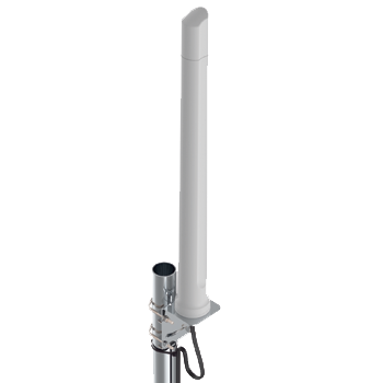
Poynting OMNI-0600 2×2 MIMO omni-directional 4G/5G antenna

OMNI-0600

2×2 MIMO6 dBiOmniIP65
Design
Vertically separated two-element 2×2 MIMO omni-directional antenna
Frequency
410–4200 MHz
Peak gain
6 dBi
Application
FWA, industrial routers, agriculture, IoT and 5G RedCap
Compatible: RUTX11, RUTM11, RUT956, RUT906 · 2 units: RUTX50, RUTM50
Poynting OMNI-0402 2×2 MIMO marine 4G/5G antenna

OMNI-0402

2×2 MIMO5.8 dBiOmniIP68
Design
Vertically separated two-element 2×2 MIMO marine antenna
Frequency
410–4200 MHz
Peak gain
5.8 dBi
Application
Marine, coastal and outdoor systems
Compatible: RUTX11, RUTM11, RUT956, RUT906 · 2 units: RUTX50, RUTM50
Poynting PANL-401 4×4 MIMO and GNSS panel antenna

PANL-401

5-in-14×4 cellularGNSS L1/L5IP65
Design
4× cellular and 1× dual-band active GNSS, omni-directional panel
Frequency
Cellular 410–6000 MHz; GNSS L1 1575.42 MHz, L5 1176.45 MHz
Peak gain
Cellular 7.8 dBi; GNSS LNA 20 ±2 dB
Application
Vehicles, rail, fixed sites, smart city and energy monitoring
Compatible: RUTX50, RUTM50, RUTC50, RUTX14 (all ports including GNSS)
Poynting OMNI-0280 wideband SISO 4G/5G antenna

OMNI-0280

SISO3 dBiOmniIP65
Design
Single-polarised wideband SISO cellular antenna
Frequency
617–960, 1427–1517, 1710–2700, 3400–4200 MHz
Peak gain
3 dBi
Application
IoT/M2M, metering and security systems
Compatible: Teltonika devices with a single cellular antenna port
TECHNICAL RESOURCES

General Antenna Technical Information

error: Content is protected !!