

Marine Antenna Installation Antenna Placement Guide for Boats
Marine antenna installation is more than fixing an antenna to the mast. The distance between antennas, and between each antenna and the mast, directly determines isolation, diversity gain and MIMO performance. This guide explains 4G/5G antenna placement on a boat with real dimensions.
Before Marine Antenna Installation: Frequency and Distance
When planning a marine antenna installation, the first question is which band the boat will connect on, and how far from the coast.
Moving away from a base station on shore, 3500 MHz drops out first, then 1800/2100 MHz; 700/850/900 MHz reaches furthest. Offshore, the connection is therefore carried by the low bands, while close to the coast capacity comes from the mid and high bands.
For placement, the consequence is this: the antenna spacings below depend on wavelength, and the low bands, with the longest wavelength, need the widest spacing. Installation dimensions should be set for the lowest frequency the boat will use.
For range calculation: 4G/5G signal distance at sea
Three Criteria for Separating Antennas
During marine antenna installation, spacing multiple antennas correctly has to meet three separate requirements at once.
Antenna isolation
Power transmitted by one antenna must not leak into the receiver of its neighbour. Insufficient isolation desensitises the receiver.
Antenna diversity
The antennas see different fading conditions, raising the chance that one receives a strong signal while the other is weak.
MIMO decorrelation
MIMO layers must be independent (uncorrelated). The more independent the layers, the higher the data rate.
The right antenna spacing is chosen by whichever of these three criteria demands the most.
Marine Antenna Installation and Isolation: Side by Side
Two omni antennas side by side at the same height see each other in their strongest direction. The higher the antenna gain, the larger the required spacing.
Curves are calculated from the formula above. At short distances, near-field effects make values approximate; leave wider spacing where possible.
| Frequency | 2 dBi | 4 dBi | 6 dBi | 8 dBi |
|---|---|---|---|---|
| 700 MHz | 0.11 m | 0.17 m | 0.27 m | 0.43 m |
| 900 MHz | 0.08 m | 0.13 m | 0.21 m | 0.33 m |
| 1800 MHz | 0.04 m | 0.07 m | 0.11 m | 0.17 m |
| 2100 MHz | 0.04 m | 0.06 m | 0.09 m | 0.14 m |
| 2600 MHz | 0.03 m | 0.05 m | 0.07 m | 0.12 m |
| 3500 MHz | 0.02 m | 0.03 m | 0.05 m | 0.09 m |
Minimum horizontal spacing for 10 dB isolation.
For an 8 dBi antenna the required spacing is about one wavelength: 0.43 m at 700 MHz, 9 cm at 3500 MHz. These are minimums; more is always better. For the fundamentals: What is MIMO isolation?
Isolation: Stacked Vertically
Marine antenna installation is often done on a narrow mast. If horizontal space is limited, antennas are placed at different heights. This layout takes advantage of the omni antenna's radiation pattern.
A good omni antenna radiates its power towards the horizon; straight up and straight down its gain is between −20 and −40 dB. Because two stacked antennas see each other in this weak direction, the same isolation is achieved at a much shorter distance than side by side.
Rule of thumb: When stacking antennas, leave at least 0.5 m between them.
Antenna Spacing for Diversity and MIMO
Once isolation is met, the second question is whether the antennas see sufficiently different signals. The measure for this is spacing in wavelengths.
1 wavelength is the minimum, 3 wavelengths a good target.
| Frequency | 1 wavelength | 3 wavelengths |
|---|---|---|
| 700 MHz | 0.43 m | 1.29 m |
| 900 MHz | 0.33 m | 1.00 m |
| 1800 MHz | 0.17 m | 0.50 m |
| 2100 MHz | 0.14 m | 0.43 m |
| 2600 MHz | 0.12 m | 0.35 m |
| 3500 MHz | 0.09 m | 0.26 m |
Diversity raises the chance that at least one antenna receives a good signal. MIMO delivers its gain when the signals received by the two antennas are uncorrelated. On a boat that also uses 700 MHz, the good target of 3 wavelengths is about 1.3 m.
Vertical or horizontal?
Vertical offshore. Reflections mostly come from below, from the sea surface. In this case, placing antennas at different heights gives better results.
Horizontal in harbour and city. Reflections mostly come from the sides, from buildings. In this case, separating antennas side by side at the same height works better.
On boats used both offshore and in harbour, combining the two, separating antennas both horizontally and vertically, gives the most balanced result. For the effect of sea surface reflection: Fresnel zone and marine antennas
Omni Antenna Near the Mast
The most often overlooked factor in marine antenna installation is the mast itself. An omni antenna is designed to radiate equally in all directions. A metal mast beside it distorts this pattern.
When the antenna is mounted on top of the mast, its radiation pattern is a full circle. When the same antenna is mounted on a bracket beside the mast, for example 110 mm away, the mast acts as a reflector: gain rises in some directions and drops by several dB in others.
The distortion increases with frequency. In measurements, the pattern stays close to a circle at 600–900 MHz, while clear peaks and nulls appear at 1700–2200 MHz.
Recommendation: Mount the antenna on the masthead if possible; if not, as far from the mast as possible, and not on the side of the mast facing away from the coast. Because the boat keeps changing heading, a weakness in one direction is eventually felt as dropped connections.
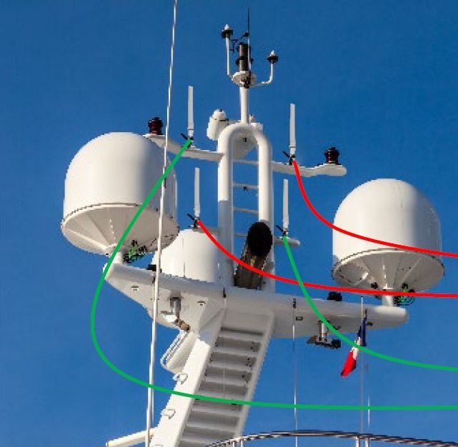
Marine Antenna Installation Examples: Dual-Modem Router
A router with two 2×2 LTE modems needs four antenna ports. The same need can be met in two different ways.
4 × OMNI-291
Four single (SISO) antennas sit on the two arms of the mast at two different heights. Each modem connects to two antennas separated both horizontally and vertically, so the two ports of each modem use the antennas furthest apart.
2 × OMNI-402
OMNI-402 is a two-port (2×2 MIMO) antenna in a single housing. The two antennas are placed at the two ends of the mast, and each modem connects to one port on each antenna. With two antennas instead of four, each modem still receives from two points far apart.
Common principle: Connect a modem's two ports to the two antennas furthest apart, not to two antennas side by side. Diversity and MIMO gain come from the separation between the ports of the same modem.
Marine Antenna Installation Checklist
- Identify the lowest frequency the boat will use; all spacings are calculated from it.
- For side-by-side antennas, provide the spacing needed for 10 dB isolation (about one wavelength for an 8 dBi antenna).
- Leave at least 0.5 m between stacked antennas.
- For diversity and MIMO, aim for at least 1, ideally 3 wavelengths of spacing.
- Prioritise vertical separation for mainly offshore use, horizontal separation for mainly harbour and city use.
- Mount omni antennas on the masthead or as far from the mast as possible.
- Connect each modem's ports to the antennas furthest apart.
- Keep cables as short as possible; cable loss quickly erodes gain, especially on the high bands.
Frequently Asked Questions
What is the minimum distance between antennas in a marine antenna installation?
Side by side, the distance depends on frequency and antenna gain; an 8 dBi antenna needs about 0.43 m at 700 MHz and 0.17 m at 1800 MHz. When stacked vertically, leave at least 0.5 m.
Should I mount antennas side by side or stacked?
Offshore, reflections come from the sea surface, so stacked (vertical) separation works better; in harbour and city, reflections come from the sides, so side-by-side (horizontal) separation works better. Combining both is the most balanced solution.
Is it a problem to mount the antenna beside the mast?
It works, but the mast distorts the radiation pattern and gain drops by several dB in some directions. The effect is stronger at higher frequencies. The best position is the masthead.
Four single antennas or two MIMO antennas?
Both suit a router with two 2×2 modems. Four single antennas give more placement freedom; two two-port antennas mean fewer mounting points and a cleaner mast.
Antenna placement for your boat
BağLAN is the official Poynting distributor for Turkey. Send us your mast dimensions and router model, and we will choose the right antennas and placement for your marine antenna installation together: bilgi@baglan.com.tr · +90 212 358 59 09