
RTK GNSS Solutions Smart Transport, V2X and Antennas
RTK GNSS reduces the metre-level error of standard satellite positioning to centimetre level. This guide covers the infrastructure, working principle and correct antenna selection needed for lane-level positioning in public transport, autonomous vehicles and V2X applications.
- 1–3 cm position
- NTRIP / CORS
- L1 · L2 · L5
- Corrections over 4G/5G
- V2X integration
What is GNSS?
GNSS (Global Navigation Satellite System) is the collective name for satellite-based positioning systems. The receiver calculates its position from the travel time of signals from at least four satellites.
GPS
US system. L1, L2 and L5 frequencies.
GLONASS
Russian system. G1, G2 and G3 frequencies.
Galileo
European Union system. E1, E5a, E5b and E6 frequencies.
BeiDou
Chinese system. B1, B2 and B3 frequencies.
With a standard receiver, ionospheric delay, orbit errors and satellite clock drift typically cause a position error of 2–5 metres. This accuracy is sufficient for navigation, but falls short for lane-level positioning, precise docking or autonomous driving.
How does RTK (Real-Time Kinematic) work?
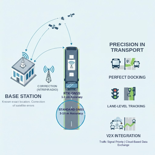
RTK GNSS measures the errors at a reference station with a known position in real time and sends these corrections to the moving receiver. It consists of three components:
- Base station: A fixed point with precisely known coordinates; it generates the correction data.
- Rover: The moving receiver on the vehicle; it applies the corrections to calculate its position.
- Data link: UHF radio modem or NTRIP over the internet; vehicles typically use a 4G/5G modem.
Instead of code measurements, RTK uses carrier-phase measurements; by exploiting the signal wavelength (about 19 cm for L1) it achieves much finer range resolution. Typical accuracy is ≈ 1 cm + 1 ppm × baseline, i.e. about 1 mm of additional error for every kilometre from the base station.
Conventional RTK vs network RTK (NTRIP)
| Feature | Conventional RTK | Network RTK (NTRIP) |
|---|---|---|
| Hardware | Own base station + rover | Rover only |
| Range | 10–20 km (limited by radio) | Anywhere with internet access |
| Cost | High initial investment | Low investment + subscription |
| Accuracy | Very high at short range | High and stable |
In Türkiye, network RTK corrections are available through the CORS-TR (TUSAGA-Aktif) network operated by the General Directorate of Mapping and the General Directorate of Land Registry and Cadastre.
RTK GNSS in public transport
On buses and BRT vehicles, a 4G/5G modem connects to the CORS network via NTRIP and receives RTCM corrections. The vehicle then knows which lane it is in and how far it is from the stop at centimetre level.
| Application | Standard GPS | RTK GNSS |
|---|---|---|
| Arrival prediction | Deviates with traffic | Lane speed and stop approach taken into account |
| Stop announcement | Early or late | Exactly at the stop |
| Fleet management | Vehicle spacing delayed | Centimetre-level, real-time |
| Signal priority | Coarse position | Lane-level triggering on junction approach |
Autonomous and electric buses
RTK is the primary position source for driverless vehicles. It also enables precise docking on wireless charging pads at stops and depots.
Accessible boarding
Docking the vehicle right at the kerb makes boarding easier for wheelchairs and pushchairs, and reduces tyre and bodywork damage.
Outage handling
When GNSS is lost in tunnels and between tall buildings, an IMU (accelerometer, gyroscope) and CAN-bus wheel speed maintain the position for short periods.
RTK in urban areas: challenges and solutions
Urban canyon effect
Tall buildings block the satellite view and reflect signals. Solution: multi-constellation reception (GPS, Galileo, GLONASS, BeiDou) to increase the number of visible satellites.
Multipath
Reflected signals corrupt the phase measurement. Solution: an antenna design that suppresses multipath, a stable phase center and mounting in the middle of the vehicle roof.
Ionospheric delay
The largest error source in a single-frequency receiver. Solution: L1/L2/L5 multi-band reception to calculate and remove the delay.
Why the antenna matters for RTK GNSS
However good the RTK receiver is, centimetre accuracy cannot be reached with a weak antenna. Four characteristics are decisive in an RTK antenna:
Multi-band
L1, L2 and L5 support for removing ionospheric delay and achieving a fast RTK fix.
Phase center stability
The electrical center remains stable at millimetre level regardless of the signal angle.
Multipath suppression
Rejection of signals reflected from buildings and vehicle surfaces; a suitable ground plane.
LNA gain
The weak satellite signal reaches the receiver cleanly despite cable losses.
Phase center stability
The antenna phase center (APC) shifts by a few millimetres depending on the elevation and azimuth angle of the incoming signal. This variation (PCV) causes errors especially in the vertical (Z) coordinate; when different antennas are used at the base and rover, the error can reach centimetre level. Calibration values are corrected in software using ANTEX (.atx) files.
ARP, APC, PCO and PCV explained, ANTEX calibration and its impact on antenna selection
GNSS antenna phase center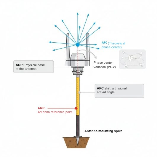
RTK GNSS antennas
There are two approaches in vehicle projects. Poynting combination antennas, which bring cellular, Wi-Fi and GNSS together in a single housing, suit fleet and V2X applications. Where the highest accuracy is required, a separate multi-band GNSS antenna with a stable phase center is preferred.
Poynting combination antennas (5G/LTE + GNSS)

SWIRL
Roof antenna for buses and special vehicles. Technical details on the Poynting SWIRL-8 product page.
- 8×8 / 4×4 MIMO 5G/LTE
- 4×4 Wi-Fi 7
- GNSS L1/L5, E-Mark

MIMO-4 series
4×4 MIMO multi-port antennas for vehicles; models with GNSS ports available.
- 4×4 MIMO 5G/LTE
- Wi-Fi and GNSS options
- Vehicle roof mounting

PUCK series
Compact IoT and vehicle antennas with IP69K housing; models with GNSS ports available.
- 2-in-1 to 4-in-1
- Cellular, Wi-Fi, GNSS
- Kiosk, bus stop and vehicle
Multi-band RTK GNSS antennas

HX-CVX600A
Full-band, survey-grade GNSS antenna.
- GPS L1/L2/L5, Galileo E1–E6, BeiDou B1–B3, L-band
- PCV repeatability ≤2 mm
- LNA 40 dB, IP67/IP69K, TNC

YEGR001W8AH
Multi-band, multi-constellation GNSS antenna.
- GPS, GLONASS, Galileo, BeiDou, QZSS, IRNSS
- L1/L2/L5/L6 and L-band
- LNA 40 dB, IP67, surface/magnetic

YEGN103W8A
Multi-band GNSS antenna with L-band support.
- 1164–1300 MHz and 1525–1606 MHz
- RTK/SBAS corrections via L-band
- LNA 40 dB, 3 m RG174, SMA/TNC
Why does RTK integration with V2X matter?
V2X enables communication between vehicles and infrastructure; RTK provides the absolute position that this communication relies on. A shared hazard warning is only as reliable as the position of the vehicle that sends it.
Lane-level position
Distinguishes whether a vehicle is in its own lane or the opposite lane.
Cooperative perception
Hazard data shared between vehicles is tied to an accurate position.
Non-line-of-sight awareness
Vehicles at junctions and in blind spots are detected before they are seen.
Roadside support
A roadside unit (RSU) can provide correction data during GNSS outages.
Example RTK + V2X system architecture
- Hybrid antennaMulti-band GNSS (L1/L2/L5) and 5.9 GHz V2X on the vehicle roof.
- CableLow-loss coaxial (LMR-240 or better), as short as possible.
- OBUGNSS receiver with a hardware RTK engine, 20 Hz or higher.
- IMUSensor fusion with a 6-axis gyroscope and accelerometer.
- C-V2X (PC5)Direct vehicle-to-vehicle and vehicle-to-infrastructure communication.
- Data flowRTCM corrections → RTK fix (2–3 cm) → position, speed and heading broadcast in the BSM message.
| Feature | Standard system | RTK + V2X |
|---|---|---|
| Position accuracy | 2–5 m | 1–3 cm |
| Lane detection | Camera only | Position and camera combined |
| Risk detection | Limited to line of sight | Including non-line-of-sight vehicles |
| Communication | Over 4G/5G, with latency | Direct via PC5, low latency |
For V2X antennas and applications, see the V2X and Poynting antennas page.
About RTK GNSS
Why RTK GNSS instead of standard GPS?
Lane-level positioning, precise docking at stops, autonomous driving and smart junction applications require centimetre, not metre, accuracy. Standard GNSS is not sufficient for these applications.
Does the system stop if the internet connection is lost?
Without correction data, the RTK fix is lost after a while and the position falls back to standard GNSS accuracy. Short outages can be bridged with the vehicle's IMU and wheel speed data; the RTK fix is re-established once the connection returns.
Is RTK infrastructure available in Türkiye?
Yes. The CORS-TR (TUSAGA-Aktif) network provides network RTK corrections nationwide. Vehicles only need an RTK receiver, a 4G/5G modem and a suitable GNSS antenna.
Combination antenna or separate GNSS antenna?
For fleet tracking, passenger information and V2X, combination antennas that bring 5G/LTE and GNSS together in one housing are practical and sufficient. If survey-grade accuracy and the shortest RTK fix time are required, a separate multi-band GNSS antenna with a stable phase center is preferred.
Is L5 support necessary?
L1/L5 dual frequency reduces ionospheric error and is more robust against multipath in urban areas. Most new-generation RTK receivers use L1/L5, so the antenna should support these bands too.