01 / MULTI-CONSTELLATION
Multi-Constellation
Supports the GPS, Galileo, GLONASS, BeiDou, QZSS and IRNSS signal families.

The V1831-297-A-01 full-band GNSS antenna provides multi-frequency reception for the GPS, Galileo, GLONASS, BeiDou, QZSS and IRNSS satellite systems.
A full-band antenna solution developed for geodetic surveying, precise positioning, RTK, mobile mapping, autonomous systems and deformation monitoring.
Global Navigation Satellite Systems (GNSS) provide position and time information using signals from different satellite constellations and frequencies.
In high-precision applications, receiving only the GPS L1 signal may not be sufficient. Multi-frequency reception helps model ionospheric delay, supports carrier-phase measurements and improves the stability of the RTK solution.
With its wide band coverage, RHCP polarization, built-in low-noise amplifier and a housing suited to harsh environments, the VLG V1831-297-A-01 full-band GNSS antenna is designed for professional GNSS systems.
Supports the GPS, Galileo, GLONASS, BeiDou, QZSS and IRNSS signal families.
An antenna platform suited to professional receivers using L1, L2, L5 and other GNSS frequencies.
A low-noise amplifier gain of 40 ±2 dB supports the RF signal level delivered to the GNSS receiver.
Specifications are based on the VLG V1831-297-A-01 datasheet. For the manufacturer's other models, see the VLG GNSS antenna product page.
Antenna gain and LNA gain are different technical quantities. LNA gain is not directly equivalent to the passive gain of the antenna.
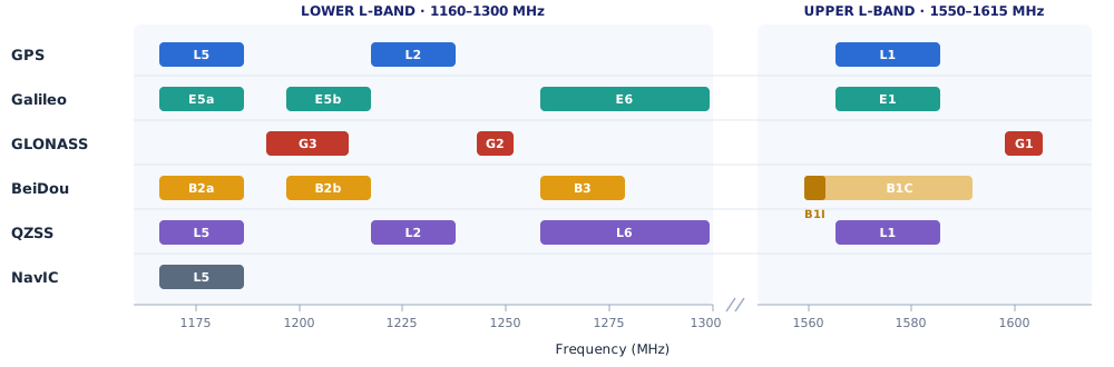
The VLG full-band GNSS antenna is designed to support multiple satellite systems and frequency groups.
| GNSS System | Supported Frequencies | Relevance for Applications |
|---|---|---|
| GPS | L1 / L2 / L5 | Multi-frequency precise positioning and RTK. |
| Galileo | E1 / E5a / E5b / E6 | Multi-frequency operation and European GNSS compatibility. |
| GLONASS | G1 / G2 / G3 | Additional satellite observations and multi-system support. |
| BeiDou | B1 / B2 / B3 families | Extended satellite and frequency coverage with BDS signals. |
| QZSS | L1 / L2 / L5 / L6 | Regional satellites and additional services supported by suitable receivers. |
| IRNSS / NavIC | L5 | Compatibility with the regional GNSS signal family. |
An antenna supporting a frequency does not mean the connected GNSS receiver can decode that signal. System compatibility should be assessed together with the receiver hardware, software and antenna supply. For details on GPS civil signals (L1C, L2C, L5): GPS.gov.
Real-Time Kinematic (RTK) is a method that delivers high-precision position solutions using GNSS carrier-phase measurements and correction data.
The VLG full-band GNSS antenna receives the satellite signals and passes them to the GNSS receiver. The RTK computation itself is performed by the receiver, together with the correction data, software and measurement conditions. For details on base stations, correction broadcasting and antenna selection, see our RTK GNSS solutions page.
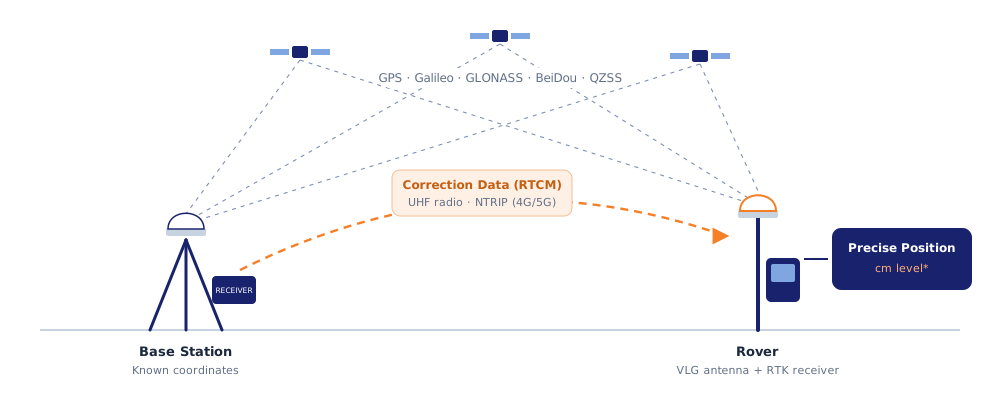
RF signals from GPS, Galileo, GLONASS, BeiDou and other satellite systems.
RHCP antenna element, multi-frequency reception and built-in LNA.
Processing of code and carrier-phase measurements, reception of RTK corrections.
Centimetre-level position solution under suitable conditions.
Centimetre-level RTK accuracy is not provided or guaranteed by the antenna alone. It depends on the receiver, correction source, satellite geometry and measurement environment.
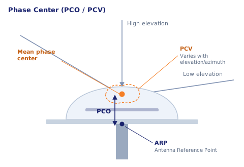
In high-precision GNSS applications, the electromagnetic characteristics of the antenna directly affect the position solution.
The Antenna Phase Center is the effective electromagnetic point to which carrier-phase measurements are referenced.
Phase Center Variation (PCV) and Phase Center Offset (PCO) are especially important in geodetic surveying and precise reference stations. For more on this topic, see our GNSS antenna phase center page.
To use an exact value for the phase center performance of the VLG full-band GNSS antenna, verified calibration data for the specific model should be applied.
Reduction of antenna-induced systematic errors in carrier-phase measurements.
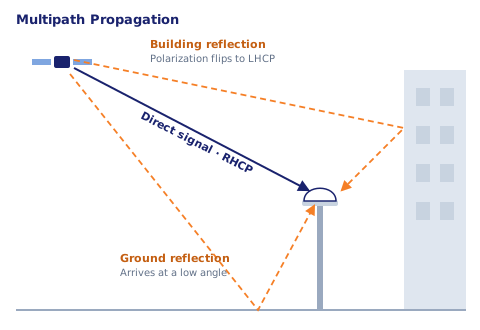
Reflected satellite signals combining with the direct signal and causing measurement errors.
Right-hand circular polarization matched to the GNSS signal structure.
Satellite elevation angle, gain pattern and multipath effects assessed together.
Cadastral, land and engineering surveys, and precise coordinate determination.
Fixed GNSS monitoring points, RTK base stations and multi-frequency positioning.
Long-term monitoring of position changes in dams, bridges, slopes and critical structures.
Precise position reference for vehicle-mounted LiDAR, camera and mapping systems.
RTK positioning for tractor guidance, seeding lines and agricultural automation.
Precise position and motion control on graders, excavators, dozers and similar machines.
Marine surveys, coastal mapping, hydrographic research and survey vessels.
GNSS receiver infrastructure for UGVs, USVs, mobile robots and precise navigation systems.
Mining, logistics, infrastructure projects and high-precision site positioning systems.
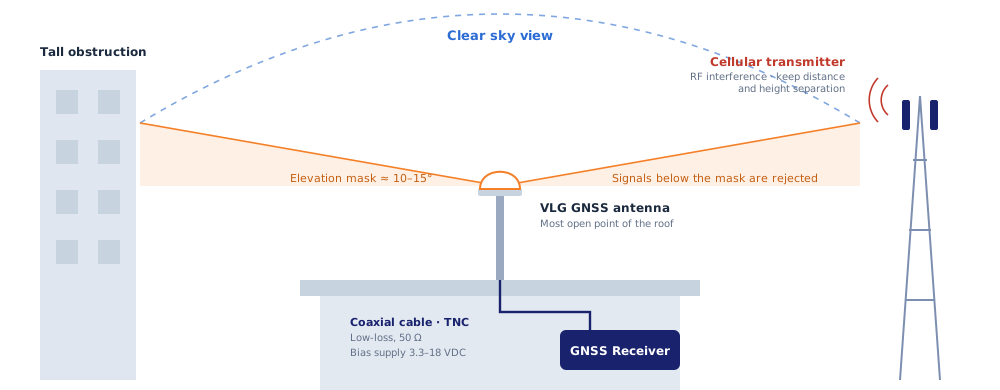
Even a good full-band GNSS antenna may not deliver the expected system performance if it is positioned incorrectly.
The antenna should be installed in a location with as clear a view of the sky as possible.
Metal structures, nearby RF transmitters, tall obstructions and reflective surfaces can affect GNSS measurement performance.
Active antenna supply, coaxial cable loss, connector compatibility and outdoor protection should be verified before installation.
An antenna position that minimises blockage of satellite signals.
Adequate separation from cellular transmitters, high-power RF systems and electronic noise sources.
Checking cable losses, 50 Ω compatibility and the TNC connector type.
The GNSS receiver must be able to provide bias voltage within the 3.3–18 VDC range.
A full-band GNSS antenna can receive signals from multiple satellite systems and GNSS frequency bands. It is used especially in multi-frequency RTK and professional surveying systems.
The V1831-297-A-01 supports GPS, Galileo, GLONASS, BeiDou, QZSS and IRNSS/NavIC frequencies.
No. Centimetre-level accuracy requires a suitable GNSS/RTK receiver, correction data, a clear satellite view and correct system configuration.
No. Antenna gain relates to the radiation and reception characteristics of the antenna. LNA gain refers to the amplification of the received RF signal by the active amplifier.
The V1831-297-A-01 uses a TNC female RF connector. A suitable coaxial cable and connector should be selected to match the GNSS receiver's interface.
Yes. The product is rated IP67 and operates from −40°C to +85°C. Mounting and cable connections must also be suitable for outdoor conditions.
Yes, it can be used in RTK base station applications with suitable multi-frequency GNSS receivers. For geodetic installations requiring high precision, phase center calibration data should also be taken into account.
Frequency tables, VSWR, antenna gain, radiation patterns, LNA characteristics, dimensions and mechanical data.
Antenna and receiver selection should be made together, taking into account frequency support, active antenna supply, cable length and the installation environment.
Let's evaluate together the full-band GNSS antenna requirements of your RTK, geodetic surveying, mobile mapping, precision agriculture, autonomous systems and industrial positioning applications.