
GNSS Antenna Phase Center APC, PCO, PCV and ANTEX
The GNSS antenna phase center is the electrical point at which the antenna measures the satellite signal, and it is not fixed. This millimetre-level shift can turn into centimetre-level error in RTK. This page explains what the phase center is, why it shifts, how it is calibrated and how it affects antenna selection.
- ARP and APC
- PCO and PCV
- ANTEX (.atx)
- IGS / NGS calibration

What is the GNSS antenna phase center?
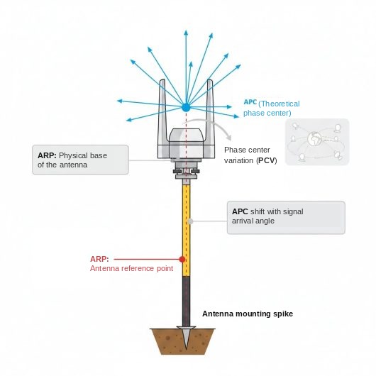
In satellite positioning, the computed point is not the outer housing of the antenna but the phase center, where the signal is received electrically. To tie a position to a point with centimetre accuracy, four concepts must be kept apart.
ARP
Antenna Reference PointThe physical, measurable reference point of the antenna; usually the center of the bottom surface where the mounting thread is located. Antenna height is measured to this point, and all calibration values are given relative to it.
APC
Antenna Phase CenterThe electrical point at which the antenna effectively receives the satellite signal. It cannot be seen and is not a physical part; its position changes with frequency and the direction of the incoming signal.
PCO
Phase Center OffsetThe three-dimensional position of the mean phase center relative to the ARP. The vertical component is usually a few centimetres, and each frequency (L1, L2, L5) has its own value.
PCV
Phase Center VariationThe deviation of the phase center from its mean position depending on the elevation angle and azimuth of the signal. It is in the millimetre range; the elevation-dependent component is usually larger than the azimuth-dependent one.
Why does the phase center shift?
A GNSS antenna cannot behave identically in every direction electrically. A satellite signal arriving at a low angle near the horizon and one arriving from directly overhead are "collected" at different points of the antenna element. As a result, the phase center:
- Varies with elevation angle: The deviation is largest for low satellites, which mainly affects the vertical coordinate.
- Varies with azimuth: Small horizontal deviations occur depending on the compass direction of the signal.
- Varies with frequency: The phase centers of L1, L2 and L5 are at different heights.
Phase center stability describes how small and repeatable these deviations are. In survey-grade antennas, PCV is kept below a few millimetres; in simple patch antennas it can be larger and harder to predict.
How does the phase center affect RTK accuracy?
Vertical (Z) error
The elevation-dependent component of PCV feeds directly into the height computation. An uncorrected phase center shows up mostly as error in the vertical coordinate.
Different antenna types
When the same antenna is used at base and rover, PCV effects largely cancel out on short baselines. With different antennas this cancellation does not occur; without correction, the error can reach centimetre level.
Antenna orientation
Because of azimuth-dependent PCV, antennas should face the same direction. This is why survey-grade antennas carry a north mark.
Antenna height
Height must be measured to the ARP and entered correctly in the software. A height entered against the wrong reference adds a constant vertical error equal to the PCO.
Multipath
The mounting surface and nearby metal structures distort the antenna's radiation pattern. Even a calibrated antenna departs from its calibration values on a poor mount.
Long baselines
As the distance between base and rover grows, satellite angles at the two points diverge; PCV effects no longer cancel and calibration becomes more important.
ANTEX and antenna calibration
Phase center errors cannot be eliminated, but they can be measured and corrected in software. For this, the antenna type is calibrated and the results are published in a standard file format.
- ANTEX (.atx): The standard file format for antenna calibrations. For each antenna type and frequency it contains the PCO value and the PCV values on an elevation/azimuth grid.
- IGS and NGS: The International GNSS Service (IGS) and the US National Geodetic Survey (NGS) publish values for calibrated antenna types. GNSS software uses these files to apply corrections automatically.
- Absolute vs relative calibration: Absolute calibration is performed with a robot-rotated antenna or in an anechoic chamber and yields the antenna's own values. Relative calibration is performed against a reference antenna; current practice is based on absolute calibration.
- Use in RTK: The base station broadcasts its antenna type and ARP height in RTCM messages. With this information, the rover software can also apply the base antenna's calibration.
Minimising phase center error
- Choose a calibrated antenna. If the antenna type is on the IGS or NGS list, the software can apply the correction automatically.
- Use the same antenna type at base and rover. On short baselines, PCV effects then largely cancel out.
- Align the antennas in the same direction. On antennas with a north mark, point the mark north.
- Measure height to the ARP. Select the correct antenna type and measurement reference in the software.
- Keep the mount clean. Install the antenna on a solid, vibration-free surface away from metal structures; on vehicles, the middle of the roof provides the best ground plane.
- Read the datasheet. Prefer antennas that state PCO, PCV or phase center repeatability values (e.g. ≤2 mm).
Choosing an RTK antenna with the phase center in mind
In projects aiming for centimetre-level positioning, it is not enough for the antenna to support the GNSS bands; phase center stability and a known calibration value are also required.
Phase center value
The datasheet should state PCO/PCV or a phase center repeatability value.
Multi-band
L1, L2 and L5 support, with the phase center of each band defined separately.
Multipath suppression
A suitable ground plane, circular polarization (RHCP) and a low axial ratio.
LNA quality
Sufficient gain and a low noise figure to compensate for cable loss.
For example, the Harxon HX-CVX600A full-band survey antenna specifies a phase center repeatability of ≤2 mm. For a multi-frequency alternative, see the VLG full-band GNSS antenna page. Antenna calibration data and ANTEX files are published by the IGS.
RTK GNSS solutions and antennas
How RTK works, NTRIP, public transport and V2X applications, and Poynting combination antennas.
About the GNSS antenna phase center
Is the phase center the same as the antenna height?
No. Antenna height is measured physically from the ground to the ARP. The phase center is usually a few centimetres above the ARP, and this difference (PCO) is added in software from the calibration file.
How many millimetres should PCV be?
In survey-grade antennas it is below a few millimetres; datasheets typically show values such as ≤2 mm. For antennas without this value, a field test is recommended when centimetre accuracy is the goal.
Does the phase center matter in vehicle projects?
Yes, in public transport, autonomous vehicle and V2X projects that require lane-level positioning. In applications where metre-level accuracy is sufficient, such as fleet tracking, its effect is negligible.
What if my antenna is not in the ANTEX list?
The software cannot apply a phase center correction. Using the same antenna at base and rover, aligning the antennas in the same direction and keeping the baseline short reduces the error. If the manufacturer provides its own calibration file, that can be used.
Does a radome affect the phase center?
Yes. That is why ANTEX records include the radome type along with the antenna type; use with and without a radome can have different calibration values.