

5 Marine Antenna TipsWhich antenna should I use with my LTE/5G router?
What to look for when choosing and installing a 4G/5G antenna on a boat: elevation and azimuth coverage, ruggedness, future frequency bands and cable loss.
The challenge: a good signal from shore-based base stations
These marine antenna tips start with one fact: in modern vessel-to-shore communication over LTE, 4G and 5G, often called "near-shore" connectivity, the main challenge for boaters is receiving a good enough signal from base stations on land.
In these marine antenna tips, "marine" does not only mean ocean-going ships. It covers every vessel using the sea, lakes and inland waterways, as well as boats moored in a marina or another sheltered location.
Most vessels now use an active internet connection for entertainment, navigation, logistics and other data. Satellite communication is often too expensive, especially for leisure boats, so mobile operators extend their coverage to coastal towns, harbors and the waters within reach of their base stations. This is great for boat owners, but it creates a dependency on receiving a signal in rough weather and heavy seas.
These marine antenna tips are based on content by Stephen Froneman, Poynting Group.
1Look for an antenna with a good vertical (elevation) acceptance angle
The first of the marine antenna tips is about the vertical plane. In rough seas, the main factors are the vessel's pitch (fore and aft) and roll (side to side). As the boat moves, the antenna tilts and the base station falls in and out of its main beam, so the antenna needs a wide vertical aperture.
Elevation is just as important when the boat is moored in a harbor or another sheltered location where base stations sit higher than the mooring. Many inland waterways, such as the Rhine, have high banks where base stations are installed well above the water, which again calls for wide elevation coverage.

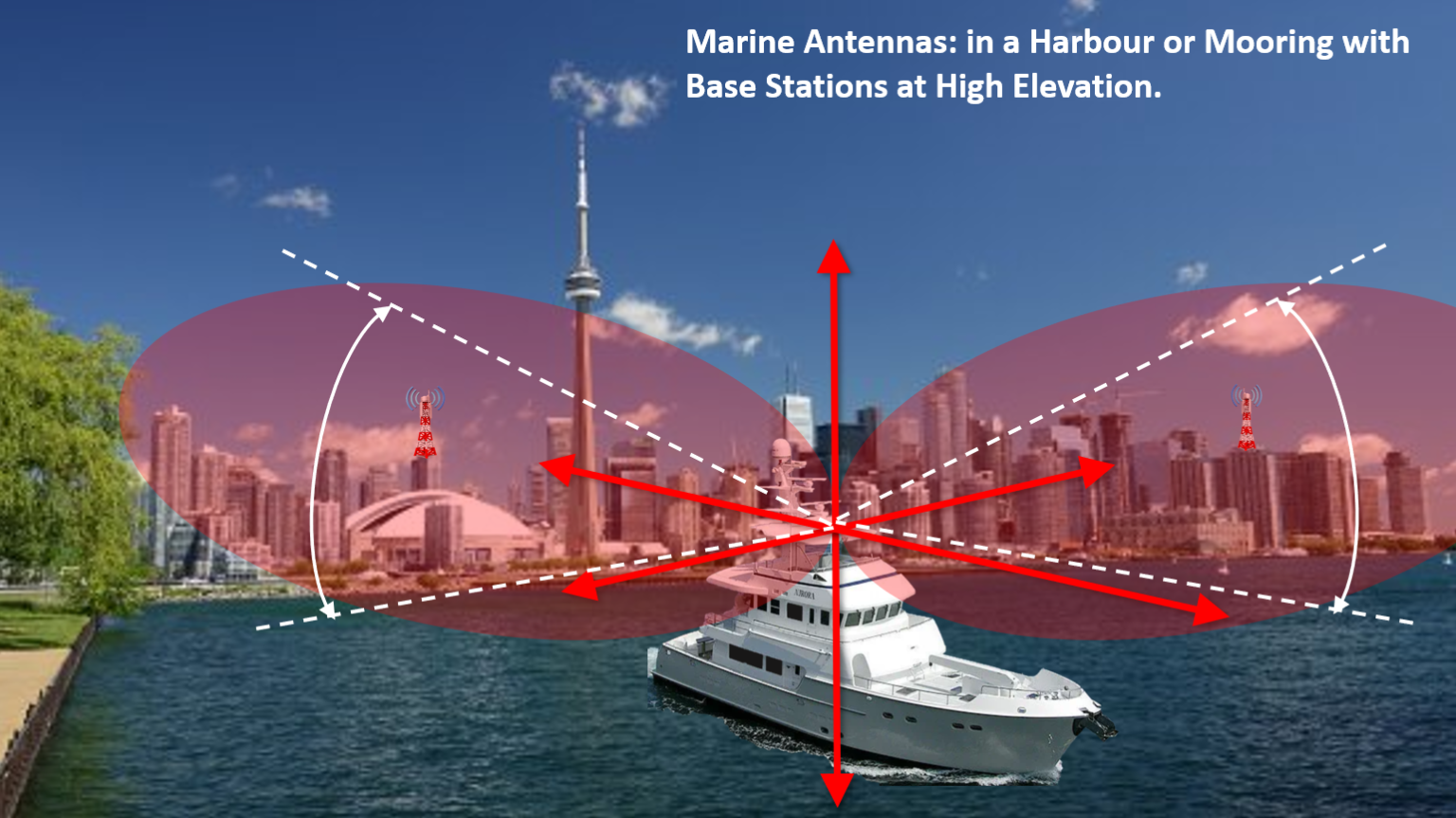

Poynting puts great effort into keeping a suitable elevation (vertical aperture) and reception efficiency across all frequency bands used by modern data systems. All Poynting documentation shows real results measured in an anechoic chamber, and the marine antennas are designed with best-in-class radiation patterns.
Check for good vertical reception when:
- the boat is pitching and rolling in rough seas;
- it is moored in a harbor or anchorage with base stations at a higher position;
- it is travelling on calm water but the base stations are higher than the vessel.

Space diversity in the vertical plane: Electromagnetic waves travelling over water tend to reflect off the surface, causing multipath: several reflected copies of the signal arrive at the receiver. Because these reflections come mostly from the horizontal water surface, they create strongly different path lengths in the vertical direction. Vertically separated antennas therefore benefit more than horizontally separated ones. With a 2×2 MIMO router, two antennas receive two different signals carrying the same data stream, turning multipath into a gain. If the vessel goes further offshore, vertical space diversity should be considered. More on this: What is MIMO isolation?
2Make sure the antenna receives well from every direction
The second of the marine antenna tips covers the horizontal plane. Selection criterion: a good horizontal acceptance angle (azimuth, 360°).
A vessel's mobility is an obvious challenge for the receiving antenna. An antenna's azimuth is its horizontal radiation pattern, its ability to receive a good signal from any direction around the vessel.
Imagine approaching a harbor and relying on a 4G/5G tower off the starboard bow at, say, 37°. If the antenna has a dip in its pattern in that direction, you can suddenly lose the approach data for your electronic chart display and information system (ECDIS).


Space diversity in the horizontal plane: If the mast allows, two antennas separated in the vertical plane are best, as noted above. Horizontal separation is an extra advantage when the vessel often travels near harbor buildings, high river banks or coastal inlets, where reflections in the horizontal plane are likely. Spacing and placement rules: Marine antenna installation
3Ruggedness: built for the marine environment
Among all marine antenna tips, ruggedness is the easiest to check. One of the most stressful situations on the water is losing communication because of a damaged or faulty antenna. All Poynting marine antennas meet at least IP65, so they withstand the harsh elements at sea and give you peace of mind that physical failure is very unlikely.
 −40 °C to +80 °COperating temperature
 Flame retardantHousing material
 IP68Salt spray, UV and storms
4Choose an antenna that supports new technologies
Future-proofing is one of the marine antenna tips that pays off for years. Base station deployment is very dynamic. Mobile network operators and internet service providers keep improving their services and use different frequency bands for new ones. An antenna bought today may not receive newly deployed services if its frequency coverage is limited.
Poynting designs its antennas to cover all frequency bands likely to be used in the future (see the Poynting product range), from the low 600–900 MHz coverage bands to the 3.5 GHz 5G band and beyond.

5Installation: keep antenna cable losses low
The last of our marine antenna tips is often the most overlooked.
Keeping cable losses to a minimum is extremely important. Apart from space diversity, the placement of and distance between the router and the antenna are the other key installation points. Commonly used cable types:
Following these marine antenna tips, where the distance between antenna and router is long, N-type connectors and low-loss cable such as LMR-240 or LMR-400 should be considered. The tables below compare the net gain with a 15.5 m cable run to the router. Connector losses are not included, so good-quality connectors and careful installation are essential when making up cables.
| Frequency | Loss/m | Cable loss | Antenna gain | Net gain |
|---|---|---|---|---|
| 900 MHz | 0.362 dB | 5.6 dB | 9 dB | 3.4 dB |
| 1800 MHz | 0.514 dB | 8.0 dB | 10 dB | 2.0 dB |
| 2400 MHz | 0.533 dB | 8.3 dB | 10 dB | 1.7 dB |
| 3000 MHz | 0.603 dB | 9.3 dB | 11 dB | 1.7 dB |
| Frequency | Loss/m | Cable loss | Antenna gain | Net gain |
|---|---|---|---|---|
| 900 MHz | 0.127 dB | 2.0 dB | 9 dB | 7.0 dB |
| 1800 MHz | 0.186 dB | 2.9 dB | 10 dB | 7.1 dB |
| 2400 MHz | 0.218 dB | 3.4 dB | 10 dB | 6.6 dB |
| 3000 MHz | 0.246 dB | 3.8 dB | 11 dB | 7.2 dB |
Result: Over 15.5 m, thin HDF-195 cable consumes most of the antenna gain, especially at higher frequencies. With LMR-400 the net gain stays around 7 dB. On long runs, either use thicker low-loss cable or place the router close to the antenna.
Summary: 5 marine antenna tips
Keep these marine antenna tips in mind before buying and installing:
- Elevation: a wide vertical aperture keeps the link alive when pitching, rolling and in harbors.
- Azimuth: a smooth 360° horizontal pattern keeps the signal regardless of heading.
- Ruggedness: IP68, UV and salt-spray resistance, −40 °C to +80 °C.
- Future bands: cover the full range from 600 MHz to 3.5 GHz and above.
- Cable: keep runs short and use low-loss cable; separate antennas vertically for MIMO.
Marine antenna tips: frequently asked questions
Which antenna should I use with my LTE/5G router on a boat?
An omnidirectional marine antenna with a wide elevation pattern, a smooth 360° azimuth pattern and coverage from 600 MHz up to at least 3.5 GHz. For MIMO routers, use a MIMO antenna or two antennas separated vertically. See the Poynting marine antennas range and the marine antenna selection guide.
Why is vertical separation better than horizontal separation at sea?
Most reflections at sea come from the horizontal water surface, which creates large path-length differences in the vertical direction. Vertically separated antennas therefore receive less correlated signals and gain more from MIMO diversity.
Is high gain always better for a marine antenna?
Not always. Higher gain narrows the vertical beam; when the boat pitches and rolls, or sits right below a high base station in a harbor, a narrow beam can miss the signal. A good elevation pattern matters as much as peak gain.
How long can the antenna cable be?
As one of the practical marine antenna tips: HDF-195 for runs up to about 10 m, LMR-240 up to about 15 m and LMR-400 for 15–20 m. Over 15.5 m, HDF-195 loses 5.6–9.3 dB between 900 and 3000 MHz, while LMR-400 loses only 2.0–3.8 dB.
How far from shore will 4G/5G work?
The upper limit is set by the radio horizon, which depends on antenna and base station heights. See 4G/5G signal range at sea and 4G/5G coverage at sea.
Put these marine antenna tips into practice
BağLAN is the official Poynting distributor for Turkey. Tell us about your boat, router and cruising area: bilgi@baglan.com.tr · +90 212 358 59 09