
 PEPLINK MAX BR1 PRO 5G · ANTENNA SELECTION
Why Poynting SWIRL-4 for the
Peplink MAX BR1 Pro 5G?
The Peplink MAX BR1 Pro 5G, with its 4×4 MIMO cellular modem and Wi‑Fi 6 access point, is a 5G router widely used on boats and vehicles. How it performs in the field is decided by the antenna it is connected to. This page compares the Poynting SWIRL-4 and the Peplink Maritime 40G using manufacturer data.
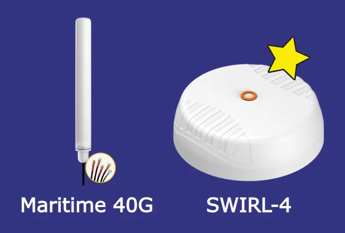
Peplink MAX BR1 Pro 5G Antenna Ports and Antenna Match
The MAX BR1 Pro 5G has seven antenna connectors: four cellular, two Wi‑Fi and one GPS. SWIRL-4 covers all seven from a single housing; Maritime 40G covers the cellular and GPS ports, and a separate antenna is needed for Wi‑Fi.
Peplink Maritime 40G vs Poynting SWIRL-4: Technical Comparison
Values are the manufacturers' published technical data. Gains are peak values.
| Feature | Poynting SWIRL-4 | Peplink Maritime 40G |
|---|---|---|
| Form factor | Low-profile dome, Ø 382 mm × 127 mm | Mast type, Ø 96 mm × 874 mm |
| Cellular frequency | 617–6000 MHz | 410–6000 MHz |
| Polarisation | Cross (+45° / −45°) | Linear |
| Cellular gain | ||
| 410–470 MHz | Not covered | 3.2 dBi |
| 617–960 MHz | 4.0 dBi | 3.8 dBi |
| 1710–2700 MHz | 6.0 dBi | 5.3 dBi |
| 3400–4200 MHz | 5.5 dBi | 6.5 dBi |
| VSWR | ||
| 410–470 MHz | Not covered | < 3.5 |
| 617–960 MHz | ≤ 2.5:1 | < 3.0 |
| 1710–6000 MHz | < 2.5 | |
| Other | ||
| Wi‑Fi | 2×2 MIMO, 2.4 GHz and 5–7.2 GHz | None |
| GNSS | GPS L1 and L5 | GPS 1575–1602 MHz |
| Protection rating | IP69K | IP68 |
| Antenna cable | 0.65 m | 2 m CFD-200 |
| Connectors | SMA (male) and RP‑SMA (male) | SMA (male) |
| Mounting | Surface, magnetic or pole | 1"-14 marine thread, pole or wall |
Maritime 40G covers the 410–470 MHz band and delivers higher peak gain at 3400–4200 MHz. SWIRL-4 offers higher gain across 617–2700 MHz and lower VSWR at 617–960 MHz.
Cross Polarisation and 4×4 MIMO
In MIMO, the modem gains throughput to the extent that it can separate the four signal paths coming from the antenna. Path separation comes either from spacing the elements apart or from giving them different polarisations.
Maritime 40G
All four elements share the same linear polarisation. Path separation relies on element spacing alone.
SWIRL-4
Elements are crossed at +45° and −45°. Polarisation diversity is used on top of spacing.
When the boat rolls, the antenna tilts with it. With a ±45° layout, both polarisation branches are affected by the tilt to a similar degree, which helps keep the branches balanced.
Explore cross polarisation technology
How Does Cable Loss Change Gain?
The gain figures given for Maritime 40G apply to the antenna element without cable. The antenna ships with 2 m of CFD-200 cable, and the loss of that cable must be subtracted from the gain. Loss increases with frequency.
SWIRL-4 has its own 0.65 m cable. When the router is placed directly below the antenna, total cable length stays short.
Maritime 40G, 2 m CFD-200 cable loss
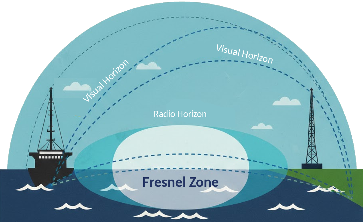
Antenna Behaviour in the Marine Environment
Protection rating
IP68defines resistance to continuous immersion in water. IP69Kdefines resistance to high-pressure, high-temperature water jets; it makes a difference in conditions such as deck washing.
Reflection from the sea surface
The sea surface is a strong reflector, and the polarisation of the reflected signal changes. A cross-polarised layout receives the direct and reflected signals on two different polarisations.
Roll and vertical beamwidth
In rough seas the antenna tilts constantly. An antenna with a wide vertical beam holds its gain towards the horizon better when tilted.
When Is SWIRL-4 the Right Choice for the Peplink MAX BR1 Pro 5G?
- Cellular, Wi‑Fi and GPS are to come from a single antenna
- A low-profile installation without a mast is preferred
- The deck is washed with high-pressure water (IP69K)
- Operation is mainly in the 617–2700 MHz bands
If the 410–470 MHz band is required, or a mast-type installation with a ready 2 m cable is preferred, Maritime 40G may be the better fit.
For the dual-5G-modem MAX BR2 Pro, SWIRL-8 or RIPPLE-8 is the match. For Starlink/OneWeb satellite integration, SpeedFusion and fleet management, see Peplink marine solutions
Peplink MAX BR1 Pro 5G and SWIRL-4: Frequently Asked Questions
How many antenna connections does the Peplink MAX BR1 Pro 5G need?
The router has seven antenna connectors: four cellular, two Wi‑Fi and one GPS. Poynting SWIRL-4 covers all seven in a single housing.
What is the main difference between SWIRL-4 and Maritime 40G?
SWIRL-4 is a cross-polarised, low-profile dome antenna with Wi‑Fi elements, rated IP69K. Maritime 40G is a linearly polarised, mast-type antenna without Wi‑Fi elements, rated IP68.
Is SWIRL-4 only for boats?
No. Besides boats, the manufacturer also specifies SWIRL-4 for vehicles, mobile platforms and remote site installations.
How are SIM cards changed when the router is installed below the antenna?
The MAX BR1 Pro 5G does not support the Peplink SIM Injector; on this model eSIM can be used to switch operators. If SIM cards need to be managed remotely from inside the boat, the SIM Injector-compatible MAX BR2 Pro is the choice.
Is the 0.65 m cable of SWIRL-4 long enough?
It is if the router can be placed directly below the antenna. For longer runs, a low-loss extension cable is used and the total loss is taken into account.