0212 358 5909 - 0212 358 5908
Çamlık Yolu Sokak Uğurlu Apt. No:4 D:7 Etiler, 34337 İstanbul

STELLA DORADUS REPEATER INSTALLATION GUIDE

Stella Doradus Repeater Installation Guide

Stella Doradus Repeater Installation: First Checks

A professional Stella Doradus repeater installation is more than physically connecting the repeater and antennas. A reliable Stella Doradus installation requires usable donor signal to be measured outdoors, the correct donor antenna to be selected, sufficient RF isolation to be created between donor and service antennas, cable losses to be controlled and the system to be verified during commissioning.

For Stella Doradus products, technical specifications and manufacturer documentation, visit the official Stella Doradus website.

1. Measure the Outdoor Donor Signal Before Installation

Signal bars on a phone provide only a rough indication. In a professional repeater design, band/cell information, RSRP, RSRQ and SINR should be assessed at the planned donor-antenna location.

RSRP: Signal Level

Shows the received reference-signal level. It does not, by itself, describe connection quality.

RSRQ and SINR: Signal Quality

Help identify whether apparently strong signal is being degraded by interference or noise.

Band and Cell Information

Knowing the target operator band and, where possible, the serving cell allows more controlled donor-antenna alignment.

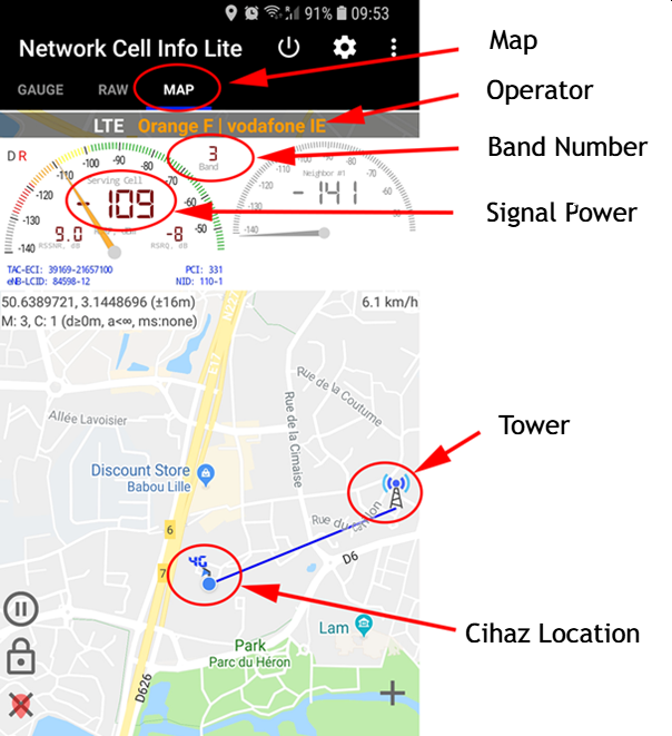
Stella Doradus repeater installation site measurement with Network Cell Info Lite
ANDROID SITE CHECK

Comparing Cellular Signal with Network Cell Info Lite

Android applications such as Network Cell Info Lite can be useful for comparing the cellular RF environment at different positions and directions before the donor antenna is installed.

  • Check the connected operator, band and cell information.
  • Compare RSRP together with RSRQ and SINR where available.
  • Repeat measurements at different positions and antenna directions.
  • Use professional RF measurements or repeater/router RF data for the final assessment where possible.
For a detailed LTE measurement guide, see RSRP, RSRQ and SINR Measurement.

2. Select the Donor Antenna According to the RF Environment

Donor-antenna selection should not be based only on antenna gain. The objective is to receive the wanted operator/cell with the best practical RF quality while limiting unwanted energy from other cells and directions.

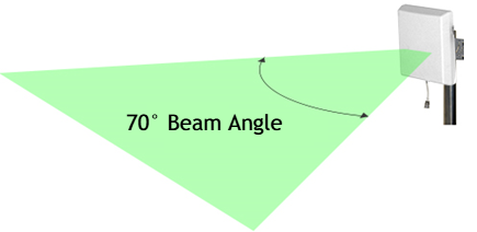
Stella Doradus wide-angle directional donor antenna
WIDE-ANGLE DIRECTIONAL

Wide-Angle Panel Antenna

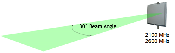
Useful where signals from a broader sector must be evaluated. Beamwidth, gain and frequency response should always be considered together with actual site conditions.


Stella Doradus narrow-angle directional donor antenna
NARROW-ANGLE DIRECTIONAL

Narrow-Angle Panel Antenna

When the target cell direction is known, a narrower beam can improve donor-cell selection and reduce unwanted RF energy arriving from neighbouring cells or other directions.
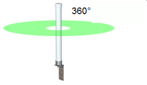
Stella Doradus outdoor omni donor antenna
360° RECEPTION

Outdoor Omni Antenna

Suitable where signal must be received from several directions. In dense RF environments it can also collect more unwanted cells and interference, so it should not automatically be the default choice.
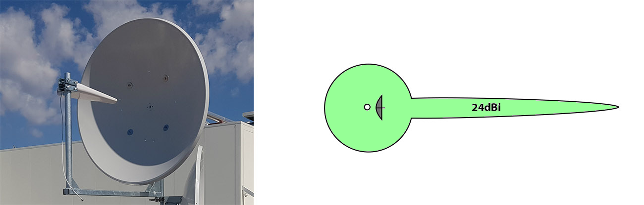
Stella Doradus high-directivity dish donor antenna
NARROW BEAM / HIGH DIRECTIVITY

Parabolic Dish Antenna

Considered for special sites requiring a very narrow beam and high directivity. High gain alone is not a sufficient selection criterion; target-cell direction and RF quality must also be verified.

Selection rule: choose the donor antenna by considering target-cell direction, RSRP/RSRQ/SINR, neighbouring cells, cable loss and the antenna's actual radiation pattern together.

3. Provide Sufficient RF Isolation Between Donor and Service Antennas

Sufficient RF isolation between the outdoor donor antenna and the indoor service antenna is critical. If energy transmitted by the service antenna is received again by the donor antenna, a feedback loop can form, causing reduced gain, unstable operation or protective functions to activate.

RF Isolation > Repeater Gain + Safety Margin

Create Physical Separation

Do not test donor and service antennas in the same room, beside the same window or in direct line of sight. Use physical distance and the building structure to create additional attenuation.

Use Vertical Separation Where Possible

A donor antenna on the roof or upper exterior facade and service antennas lower inside the building can benefit from floor slabs, concrete and other structural attenuation.

Point Antennas Away from Each Other

The directional donor antenna should face the target base station outside the building, while indoor service antennas should be oriented away from the donor direction wherever practical.

Verify at the Final Mounting Positions

Isolation must be assessed after the antennas and actual RF cables are installed. A temporary bench test in one room does not represent final site behaviour.

Oscillation detection and automatic gain control help protect the network and repeater, but they do not replace correct antenna placement and sufficient physical RF isolation.

4. Check RF Cables and Connector Connections

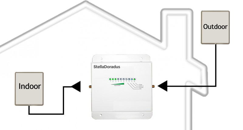
The RF path from the donor antenna to the repeater and from the repeater to the service antennas directly affects system gain and stability. Excessive cable length, unsuitable cable and poorly installed connectors can significantly reduce system performance.

Account for RF Cable Loss

  • Avoid unnecessary cable length.
  • Use application-appropriate low-loss 50 Ω RF cable.
  • Do not sharply bend or mechanically crush the cable.
  • Protect outdoor connections against water and moisture ingress.

Connect to the Correct Repeater Ports

  • Start threaded connectors carefully to avoid cross-threading.
  • Do not leave RF connectors loose.
  • Minimise unnecessary adapters and intermediate connections.
  • Check connector surfaces for corrosion or physical damage.
Total RF-path loss must be considered as a system. Antenna gain should be evaluated together with cable loss, connector loss, splitters/taps and the actual installation conditions.
On compatible Stella Doradus systems, PortSense helps verify the antenna, RF cable and connector connection chain. It is a connection-verification function, not an RF signal-quality measurement system. View PortSense Technology.

5. Plan Indoor Service Antennas According to Coverage Geometry

Indoor antenna type and location should be selected according to the floor plan, wall and floor losses, corridor geometry, usage areas and the RF isolation required from the donor antenna.
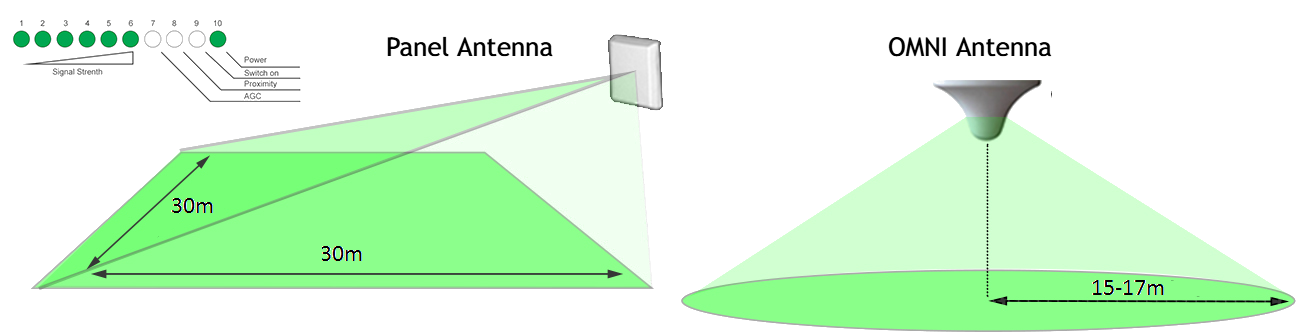
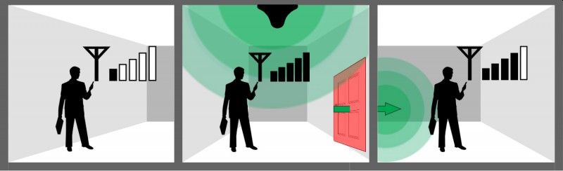
Stella Doradus indoor antenna coverage geometry example
Example indoor antenna coverage geometry.
Stella Doradus indoor RF propagation through building areas
Building elements and doorways can significantly affect indoor RF propagation.

Ceiling Omni Antennas in Open Areas

Open offices, shops and halls can use ceiling omni antennas for surrounding coverage when mounting height and placement are appropriate. Metal ceilings, columns and ventilation ducts should be considered.

Directional Antennas in Corridors and Long Areas

Long corridors and areas where coverage needs to progress in a specific direction can use directional panel antennas for more controlled RF distribution.

Account for Wall and Floor Losses

Reinforced concrete, structural walls, fire doors, metal cladding and low-emissivity glazing can substantially reduce cellular-signal propagation inside a building.

Divide RF Distribution in Large Buildings

Large or multi-floor buildings may require splitters/taps and multiple service antennas. Cable and passive losses in each branch must be included in the design.

There is no universal fixed coverage radius for an indoor antenna. Actual coverage depends on frequency band, repeater output level, antenna type and gain, cable losses, building materials and indoor geometry.

6. Stella Doradus Repeater Installation: LED Indicators and Commissioning

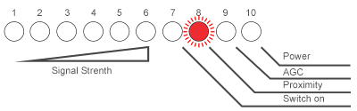
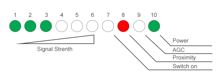
When the donor antenna is pointed toward a base station, the green signal LEDs on compatible Stella Doradus repeaters provide a quick visual indication of received donor-signal level.

Stella Doradus repeater LED signal indicators

Green LEDs – Donor Signal Level

The number of illuminated green LEDs provides a practical indication of received donor-signal level. Compare the LED level while adjusting the donor antenna in small steps, then secure the antenna after identifying the most stable direction.

Blue LED – Uplink Activity

On compatible Stella Doradus models, the blue LED can indicate uplink activity from the user device toward the repeater. Illumination during a call or mobile-data session can be normal.
LED indicators are a quick installation aid, not a substitute for professional RF assessment. Donor-signal level, signal quality and real voice/data performance should also be verified.

Common Stella Doradus Repeater Installation Errors

Stella Doradus donor and service antenna port connection example
Donor and service antennas must be connected to the correct repeater ports.
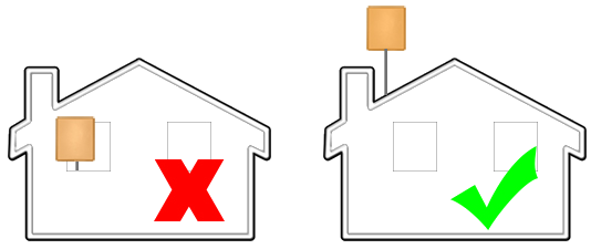
Stella Doradus incorrect and correct donor antenna mounting example
Move the donor antenna away from RF-obstructed positions and confirm the mounting point by measurement.
Testing donor and service antennas in the same environment This can create RF feedback and oscillation, causing gain reduction or protective operation.
Connecting the donor antenna to the wrong repeater port Donor and service antennas must be connected to their designated RF ports.
Installing the donor antenna at an RF-obstructed location Metal structures, walls or blocked RF paths can significantly weaken the donor signal.
Failing to align a directional donor antenna with the target cell Nearby unwanted cells can become dominant if antenna direction is selected only by raw signal level.

Poor Voice Quality or Dropped Calls

Poor voice quality or dropped calls are not determined only by indoor signal strength. Donor-signal quality, antenna type and direction, surrounding cell structure and repeater operating conditions should be considered together.

Weak Donor Signal

In rural or distant sites, the signal at the donor-antenna location can be weak or low quality. A stronger or more directional donor-antenna solution and a better mounting location may be required.

Too Many Strong Cells Reaching the Repeater

In dense urban RF environments, an omni donor antenna can receive several strong cells at once. A directional antenna can help improve target-cell selection and reduce unwanted directions.

Automatic Gain Control and Proximity Control

Automatic Gain Control (AGC) adjusts repeater gain when donor input levels become high. Proximity-control behaviour helps the system remain controlled when a repeater is close to a base station or exposed to unusually strong RF levels.
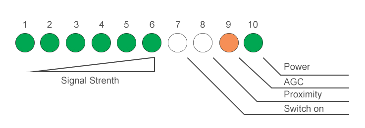
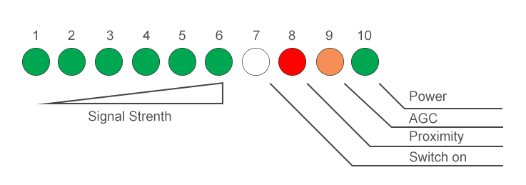
Stella Doradus automatic gain control LED example 1
Strong donor input can cause automatic gain reduction.
Stella Doradus automatic gain control LED example 2
Very strong RF conditions can activate proximity-related control behaviour.
Stella Doradus automatic gain control LED example 3
Protection indicators should be interpreted together with site conditions.
Stella Doradus automatic gain control LED example 4
AGC does not replace correct antenna placement, isolation and commissioning.
AGC and proximity control are protection and balancing functions. They do not replace correct donor-antenna choice, antenna alignment, RF isolation or professional commissioning.

Coverage Planning for Large Buildings

Hotels, multi-room offices, hospitals, shopping areas and other large buildings may require several indoor service antennas. Coverage should be planned around corridor length, room layout, wall and door losses, floor-to-floor attenuation and the antenna types used.

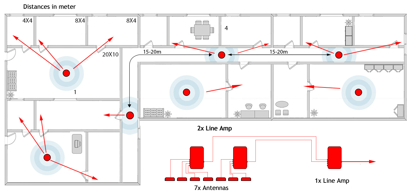
Stella Doradus indoor service antenna coverage distance example
Illustrative antenna spacing only; actual spacing must be determined by RF design and site conditions.
Stella Doradus multiple indoor antennas in a large building
Large-building coverage can require multiple service antennas and controlled RF distribution.
The antenna distances shown in example drawings are not fixed design values. Final placement should be determined using site measurements, building materials, cable/splitter losses and the required indoor coverage level.

Related Stella Doradus Technical Resources

error: Content is protected !!