Distance from Shore
Distance to the donor base station, line of sight, operating frequency and base-station direction determine the usable signal available at the platform.


OFFSHORE 4G 5G COVERAGE • OIL & GAS
Offshore 4G 5G coverage on oil & gas platforms is not created simply by selecting a repeater. It requires measuring the available mobile network environment, designing the donor link, planning deck-by-deck RF distribution, calculating cable and splitter losses, and continuously monitoring the system.
The Stella Doradus approach addresses the complete RF chain, from site survey and StellaPlanner design to Titan iRepeater and LineAmp-based distribution, followed by remote monitoring with StellaControl.
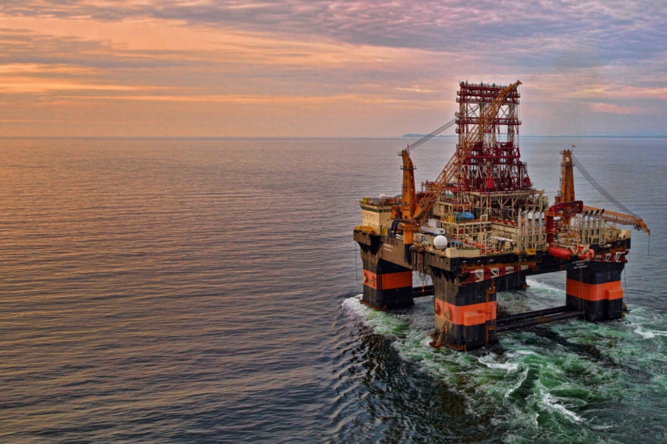
OFFSHORE RF ENVIRONMENT
In offshore 4G 5G coverage design, a strong outdoor mobile signal does not mean the same coverage will be available inside cabins and enclosed areas. The physical structure of the platform and the RF environment must be evaluated together.
Distance to the donor base station, line of sight, operating frequency and base-station direction determine the usable signal available at the platform.
Steel walls, decks, fire doors and machinery spaces can significantly attenuate RF signals.
Accommodation areas, control rooms, corridors and operational spaces should be treated as separate coverage zones with different RF conditions.
Repeater bands should not be selected before the target operators, active 4G/5G bands and actual serving cells at the site have been measured.
STELLA DORADUS ENGINEERING WORKFLOW
DONOR RF DESIGN
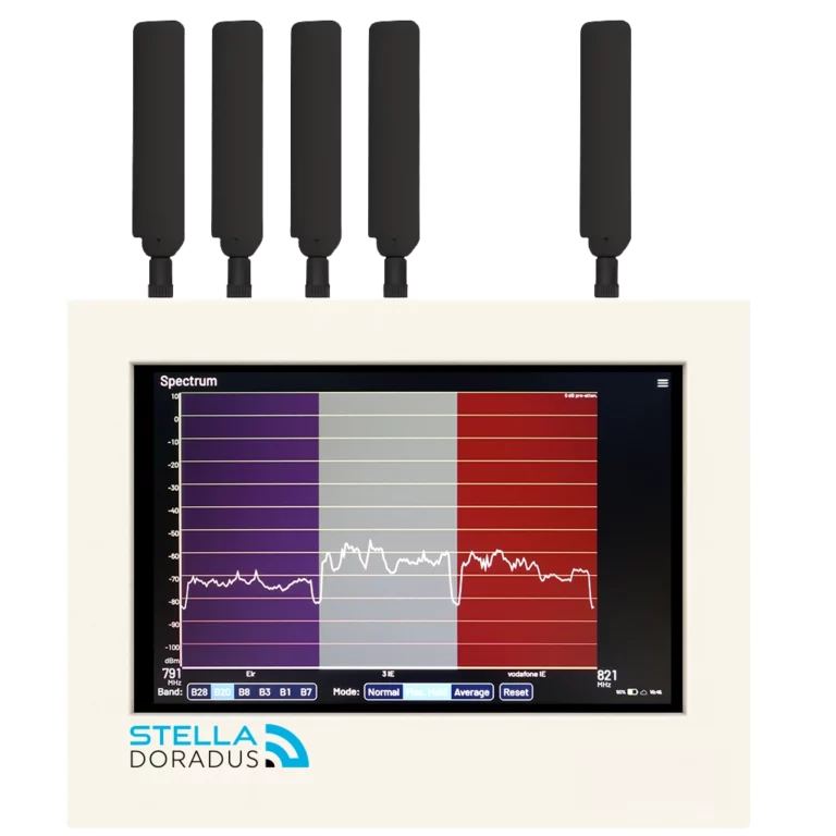
The donor antenna is installed at a suitable high point on the platform and optimized toward the base stations of the required mobile operators. Signal level alone is not sufficient; signal quality and serving-cell information are also evaluated.
IN-PLATFORM RF DISTRIBUTION
In offshore 4G 5G coverage distribution, the expected RF level is calculated for every deck and critical indoor area. The objective is not maximum gain, but balanced, stable and manageable coverage across the service antennas.
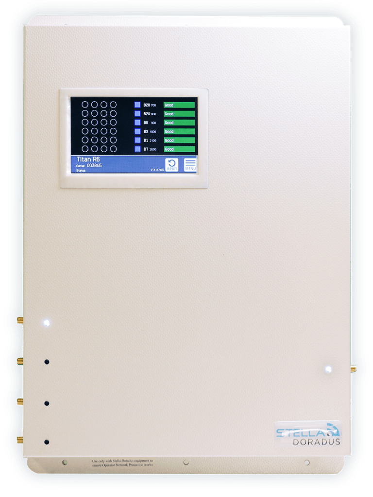
MODULAR RF DISTRIBUTION
As an offshore 4G 5G coverage system grows, it is not limited to a single service antenna. The RF distribution network can be extended to different decks and areas using splitters and, where required, LineAmps. Cable loss, splitter loss and the target RF level at each service antenna are calculated for every distribution branch.
LINK BUDGET AND RF BALANCE
Donor antenna gain, cable loss, outdoor RF level and usable signal quality are evaluated together.
Splitter, cable and LineAmp losses are calculated to achieve the target RF level at each service antenna.
Adequate isolation between donor and service antennas helps prevent oscillation and unnecessary gain reduction.
SURVEY AND PLANNING TOOLS
SHARK is used to measure outdoor cellular RF conditions, identify available operators and bands, and collect the field data required for donor-system design.
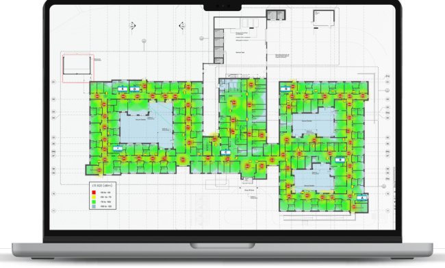
StellaPlanner is used to plan repeater, cable and service-antenna placement on deck and building plans, evaluate RF losses and prepare the project BOM.
CONTINUOUS RELIABILITY
For offshore 4G 5G coverage systems, site visits can be costly and time-consuming. Remote monitoring of the repeater system is therefore an important part of operational reliability.
Repeater performance, signal levels, settings, alerts and historical status information can be monitored remotely over the internet.
Helps periodically check the available cellular networks and base stations in the surrounding RF environment.
Helps monitor the status of antennas, cables and RF connections and provides early warning when a connection problem occurs.
GENERAL EXAMPLE FROM A REAL-WORLD DEPLOYMENT
In a project carried out by Stella Doradus, the mobile signal received through an external donor antenna on a steel offshore platform located far from shore was distributed across multiple decks.
Every platform has different distances from shore, operators, active frequencies, outdoor signal levels, deck plans and cable routes. The number of repeaters, LineAmps and service antennas must therefore be recalculated for each project.
The value of the case study is not in a fixed quantity of products, but in the engineering method: measuring the external donor signal, receiving it with a directional antenna, supporting long RF distribution runs with LineAmps and creating coverage deck by deck.
On offshore oil & gas platforms, equipment location, Zone classification, power infrastructure and cable routing must be evaluated according to the platform's hazardous-area requirements. The fact that a product has been used in an offshore project does not automatically mean that it is certified for every Zone.
Placement of the repeater and other active equipment in safe/non-hazardous areas, as well as external antennas, cable penetrations, bonding/grounding, surge/lightning protection and marine-environment mechanical mounting, must be verified on a project-specific basis.
PROJECT INPUTS
BağLAN supports the technical design and sizing of Stella Doradus solutions, from donor RF analysis and deck-by-deck coverage to remote monitoring.