Yagi Antenna
- Very large and open areas
- Where coverage is required in a specific direction
- Wide corridors
It helps concentrate the RF signal in a specific direction and carry it in a controlled way toward more distant points.
Stella Doradus indoor antenna selection and placement is one of the fundamental RF design steps for creating correct indoor coverage in GSM repeater systems. In a GSM repeater system, the indoor antenna is the final element that distributes the RF signal from the repeater output into the target coverage area. Antenna type and placement should be determined according to building geometry, wall and floor losses, ceiling height, corridor layout and the way the coverage area is used.
In Stella Doradus indoor antenna applications, ceiling-mounted omni antennas can be used in open areas, while panel antennas may be preferred in corridors or groups of rooms where directional coverage is required. In large or heavily partitioned buildings, multiple indoor antennas should be planned together with suitable RF distribution components. When selecting a Stella Doradus indoor antenna, mounting position and the target coverage direction should be considered together with antenna type.
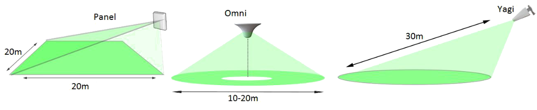
Stella Doradus offers three types of indoor antennas: Panel, Omni and Yagi.
It helps concentrate the RF signal in a specific direction and carry it in a controlled way toward more distant points.
When ceiling mounted, it distributes the RF signal evenly around the antenna and provides centralised coverage.
It distributes RF energy into a broad directional coverage area. The main coverage direction should be determined according to antenna placement and the geometry of the target area.
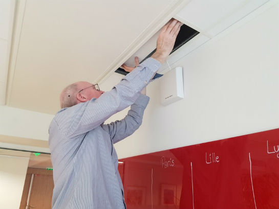
A panel antenna can be wall mounted facing a room or corridor.
Where possible, the antenna should be mounted above the occupied area and its main radiation direction should be aimed toward the target coverage area. A slight downward tilt can help direct RF energy toward the intended occupied area.
Stella Doradus indoor panel antennas use a directional radiation pattern. The actual antenna gain and beamwidth should be verified for the model used. Coverage depends not only on antenna gain, but also on repeater output level, frequency band, cable loss, wall and door construction and overall building geometry.
Because a panel antenna is directional, its mounting angle directly affects the coverage area. The main beam should be directed toward the target area occupied by users. When the antenna is mounted at a high point, a slight downward tilt can help distribute RF energy more effectively into the intended coverage zone.
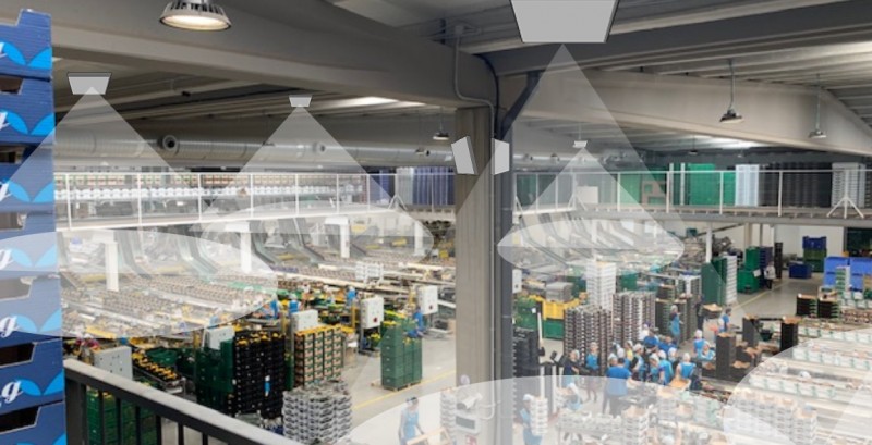
An indoor omni antenna is used to distribute the RF signal evenly around the antenna. It can be ceiling mounted particularly in open-plan offices, halls, shops and other indoor areas where centralised coverage is required.
The antenna should be positioned as close as practical to the centre of the area to be covered. Reinforced-concrete columns, metal ceiling elements, ventilation ducts and thick partition walls can affect RF propagation, so placement should not be based on the geometric centre alone.
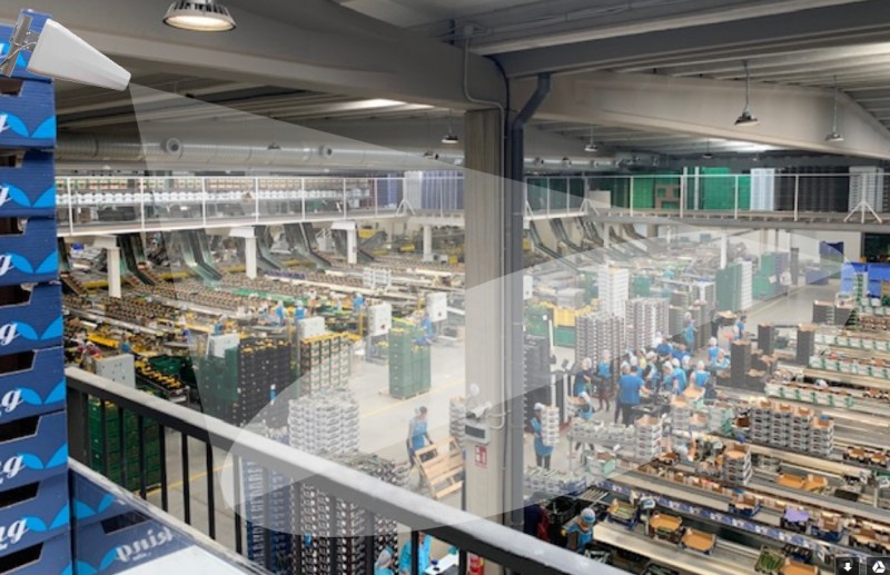
An indoor Yagi antenna can be used in large and long areas where the RF signal must be carried in a specific direction. Its directional design concentrates signal energy toward the target area in front of the antenna.
When mounted at a high point, the main beam should be directed toward the occupied area. Where required, the antenna can be tilted downward so that coverage is formed more effectively over the target zone.
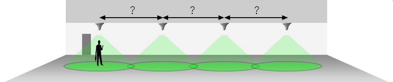
The distance between antennas inside a building depends on several factors. There are three main factors:
By a rural area, it is assumed that there are fewer than five base stations in your area. In a city, there may be 10–100 base stations around your building.
However, if you are in a rural area and the signal on the roof is good, you can place your antennas approximately 30 m apart.
In a city, the spacing between indoor antennas will need to be reduced to approximately 15 m, regardless of the signal strength on the roof.
As you can see, there is a significant difference between urban and rural antenna placement.
This applies only to rural areas. Full signal bars on your phone can be considered a strong signal for a rough check. In rural areas, the stronger the signal on the roof, the greater the possible distance between indoor antennas. Antennas can be spaced up to approximately 30 m apart.
Sometimes the signal on the roof of a rural building can be very weak, for example around three bars on a phone. In this case, the antennas should be placed approximately 15 m apart.
Some installations do not require 1800, 2100 and 2600 MHz. These installations are therefore often much easier. In rural areas, sometimes only 800 MHz and 900 MHz are available. In this case, fewer indoor antennas and therefore less equipment, such as repeaters or line amplifiers, may be required.
Panel antennas are generally mounted on walls above head height. If they are mounted more than 1 m above head height, tilt the antenna slightly downward to focus the main RF energy toward mobile-phone users.
Keep antennas away from nearby metal objects, as metal can attenuate and distort the signal.
When choosing antenna positions, prioritise important rooms, such as meeting rooms and executive offices.
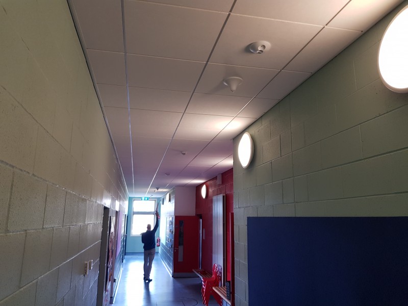
Antennas can also be installed in corridors. The signal can pass from these antennas through wooden, plastic or glass doors into rooms opening onto the corridor, as illustrated below.

One of the most difficult repeater installations is in tall, older buildings in large cities.
The reason is that mobile signal may already “leak” into these buildings. Older buildings may not have high levels of RF-shielding insulation, such as metal-backed insulation inside the walls. Windows may also be older and may not contain a metal-oxide coating. Mobile signal can therefore enter the building naturally from outside.
The problem is that this naturally entering signal is often not strong enough, or may be too distorted, to provide a good-quality mobile voice call.
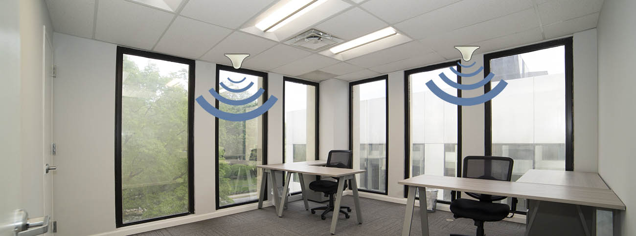
A correctly installed repeater system should be able to overcome this low-quality signal. An important aspect of installation in this type of building is to position indoor antennas near the windows. This helps phones connect to the indoor antennas rather than to the signal entering through the windows.
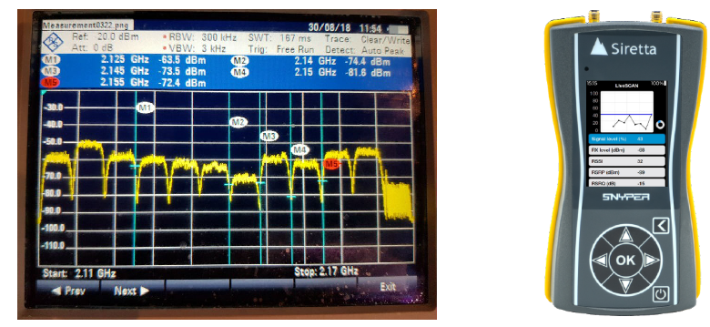
After the installation is complete, it is recommended that all indoor antennas are checked. The best method is to use a spectrum analyser with a Yagi antenna. A more economical method is to use a Siretta Snypper test instrument with a Yagi antenna. Point the Yagi antenna toward an indoor antenna from a distance of 2 m and measure the signal strength using the spectrum analyser or Siretta Snypper.
Remember that the measurement is made across the complete band. The same band should be measured for every indoor antenna.
For example, when measuring the 2100 MHz band, the band starts at 2110 MHz and ends at 2170 MHz (70 MHz bandwidth). The average power across this complete spectrum is then evaluated. A typical result may look like the example below. In this case, the average power is around -60 dBm, which is considered a strong signal.
If one particular antenna shows a much lower signal level, this indicates a possible problem with that antenna. A poorly installed cable connector is often the cause.
Web alanımızı en uygun hale getirmek için programlar kullanıyoruz.