
LMR Cable Insertion Loss: SMA, N-Type and Lightning Arrester
LMR cable insertion loss across 4G/5G bands for LMR-200 and LMR-400 assemblies with SMA and N-type connectors and the POYNTING A-RFLA-SMSF-070 lightning arrester.
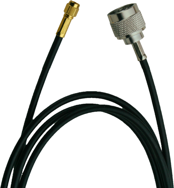
SMA to SMA cable assembly
| Band | Freq. | SMA pair typ. / max |
LMR-200 dB/m |
LMR-400 dB/m |
Arrester A-RFLA-SMSF-070 |
Total LMR-200 |
Total LMR-400 |
Comparison |
|---|
Antenna (N-type) → LMR cable → Lightning arrester → Router (SMA)
| Band | Freq. | N pair | 2 × SMA pair | Arrester | LMR-200 cable |
LMR-400 cable |
Total LMR-200 |
Total LMR-400 |
Comparison |
|---|
Assumptions
- Connector loss per mated SMA pair:
0.03·√f(GHz)dB typical,0.06·√f(GHz)dB maximum. - Connector loss per mated N-type pair:
0.03·√f(GHz)dB typical,0.05·√f(GHz)dB maximum. - LMR-200:
α(dB/100 ft) = 0.3234·√f + 0.0003·f, f in MHz. - LMR-400:
α(dB/100 ft) = 0.1223·√f + 0.00026·f, f in MHz. - POYNTING A-RFLA-SMSF-070 lightning arrester (DC–7 GHz, SMA female / SMA male): insertion loss ≤ 1.0 dB, VSWR ≤ 1.4:1. The arrester adds one extra mated SMA pair, included automatically in the total.
- Nominal cable values at 20 °C, based on Times Microwave Systems LMR® cable data.
- Arrester data: POYNTING RF Lightning Arrester.
Notes
- LMR-400 has about 60% lower loss than LMR-200 across all bands.
- LMR-400 (10.3 mm) is usually terminated with N-type; a short LMR-200 pigtail to SMA avoids mechanical stress on the router port.
- For runs under 1–2 m, LMR-200 is easier to route and the difference stays below 0.5 dB.
- Keep all MIMO chains the same length to avoid imbalance.
- Scenario 2: the N male end mates directly with the antenna; the SMA male end plugs into the arrester, which mounts directly on the router port. Support the LMR-400 cable near the arrester to keep load off the SMA joints.
- Use one arrester per RF chain (4 for 4×4 MIMO), installed close to the router entry point with a short, direct ground connection.
LMR cable insertion loss: FAQ
What is LMR cable insertion loss?
LMR cable insertion loss is the signal power lost along a coaxial cable assembly, including its connectors, expressed in dB. It rises with frequency and cable length: 5 m of LMR-200 loses 1.44 dB at 700 MHz but 3.31 dB at 3500 MHz (n78).
LMR-200 or LMR-400: which one should I use?
LMR-400 has about 60% lower LMR cable insertion loss than LMR-200 in every 4G/5G band. For runs longer than 3 m, LMR-400 is the better choice; for short runs under 1–2 m, LMR-200 is easier to route and the difference stays below 0.5 dB.
How much loss does a lightning arrester add?
The POYNTING A-RFLA-SMSF-070 adds up to 1.0 dB, plus one extra mated SMA pair. See Poynting lightning arrester for installation and grounding.
How does cable loss affect a 4G/5G router?
With passive antennas, every 3 dB of LMR cable insertion loss halves the signal power reaching the router and lowers RSRP and SINR on the uplink and downlink. Use the modem router connection analysis tool to evaluate RSRP, RSRQ and SINR values.
What is the loss of a 10 m LMR-200 cable?
At 1800 MHz, 10 m of LMR-200 loses 4.68 dB; at 3500 MHz the loss rises to 6.62 dB. An example is the 4G/5G outdoor omni antenna supplied with 10 m LMR-200 cable.